How to choose electrical terminals and connectors for automotive wiring systems
Start with the job the connection must do
Choosing electrical terminals and connectors for automotive wiring is more than matching a part number in a catalog. A reliable connection must carry the required current, tolerate heat and vibration, resist moisture where needed, remain serviceable, and fit the validation expectations of the vehicle program. The selection process should begin with the circuit function and installation location, then move through wire size, terminal geometry, sealing, material, locking features, tooling and test standards.
This approach matters as vehicles add more sensors, control modules, driver-assistance systems and electrified powertrains. For more articles in this area, visit the Electrical Components section.
The practical objective is to select the complete connection system, not only the visible plastic housing or metal contact.
Understand terminals, connector housings and the complete connection system
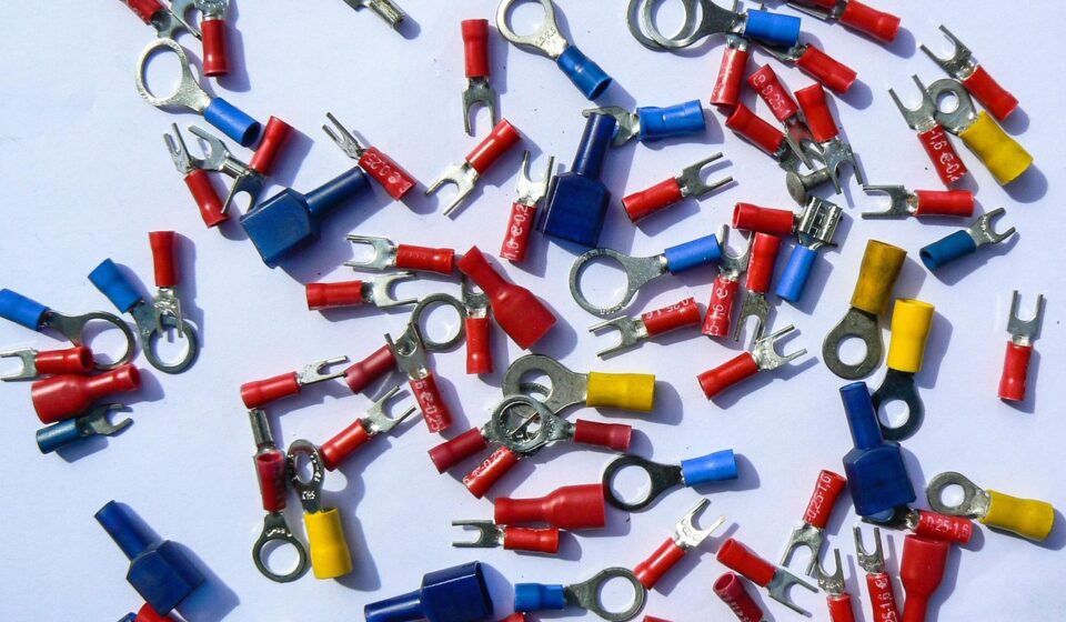
A terminal is the conductive contact attached to a wire and mated with another contact. A connector is the broader assembly that positions, protects and retains those terminals. In vehicle wiring, the connection system can include terminals, plastic housings, wire seals, interface seals, terminal position assurance features, connector position assurance locks, secondary locks, strain relief, clips, headers and service tools.
This distinction is important because many electrical failures are system failures rather than single-part failures. A terminal may have enough current capacity on paper, but the connection can still fail if the crimp is poor, the housing does not control alignment, the seal is damaged during assembly, or the latch allows micro-movement under vibration.
- Terminal geometry affects contact area, insertion force, spring behavior and resistance stability.
- Housing design controls terminal spacing, polarization, mating direction and protection from accidental damage.
- Sealing components help keep water, dust and contaminants away from the contact interface in exposed locations.
- Locking and assurance features reduce the risk of partial mating, terminal back-out and service errors.
- Tooling and process control determine whether the terminal performs as designed after crimping.
For purchasing and engineering teams, the better question is not simply which connector fits the wire. It is which validated connection system fits the circuit, environment, assembly process and service expectation.
Match connector type to vehicle location and circuit role
Automotive connectors are usually selected by application area. A cabin switch, wheel-speed sensor, battery-management harness, fuse box, lamp assembly and high-voltage power unit all place different demands on the connection. The same rated current or pin count does not make two connector families interchangeable.
Low-voltage signal and power connections
Most conventional automotive wiring still depends on low-voltage signal and power circuits. These connections support lighting, switches, relays, sensors, actuators, infotainment units, body control modules and many other functions. Selection normally focuses on current load, wire size range, pin count, packaging space, temperature exposure, mating cycles and whether the connection sits in a sealed or unsealed environment.
Low-current signal circuits can be sensitive to contact resistance stability, fretting corrosion and electromagnetic noise. Higher-current low-voltage circuits require closer review of temperature rise, contact normal force, conductor size and derating. A connector that works inside a dry cabin module may not be suitable near a wheel arch, in the engine bay or on an underbody harness without additional sealing and mechanical protection.
High-voltage EV connections
Electrified vehicles add another layer of risk and complexity. The International Energy Agency reported in its Global EV Outlook 2026 that electric car sales exceeded 20 million in 2025 and reached about one quarter of global car sales. That shift increases the importance of high-voltage interconnects, battery-pack interfaces, power electronics, onboard chargers, DC-DC converters and related control wiring.
High-voltage vehicle connections are not simply larger versions of 12 V connectors. They may require touch protection, shielding, creepage and clearance design, high-voltage interlock functions, robust sealing, color identification and validation within the vehicle safety architecture. In the United States, the e-CFR text for FMVSS No. 305a lists mandatory applicability beginning September 1, 2027, and treats high-voltage powertrain safety around thresholds such as more than 30 VAC or 60 VDC working voltage. That regulatory context does not replace connector-level engineering, but it shows why EV connection choices must be integrated with full vehicle safety requirements.
Data, sensor and mixed-signal connections
Advanced driver-assistance systems, cameras, radar, telematics and infotainment functions can require data connectors or hybrid assemblies that carry power and signal in the same package. In these applications, mechanical fit is only one part of the decision. Impedance control, shielding, contact stability, cable termination method and routing discipline can be as important as current rating. Mixed layouts should be reviewed carefully so that power load, data integrity and service access do not compromise each other.
Use standards as a validation map, not a shopping shortcut
Standards help define test language and performance expectations, but they do not automatically approve a connector for every vehicle. OEM drawings, supplier specifications, regional rules and application-specific validation plans still control the final decision. Publicly available standard descriptions are useful for understanding scope and terminology.
| Reference | What it helps define | How to use it in selection | Important limit |
|---|---|---|---|
| ISO 8092-5:2021 | Terms, test methods and general performance requirements for single-pole and multi-pole connections used with on-board road-vehicle wiring harnesses | Use it to frame connector operation, mating and unmating considerations, and general performance expectations for serviceable harness connections | It does not cover every internal electronic-device connection or every special OEM requirement |
| SAE/USCAR-2 | Performance testing for automotive electrical connector systems within its stated low-voltage road-vehicle scope | Use it as a reference point for validation discussions involving terminals, connectors and connection-system durability | Its public scope is not a blanket approval for high-voltage EV connectors or unrelated terminal styles |
| IEC 60529 | IP Code classification for degrees of protection provided by enclosures | Use IP language carefully when comparing dust and water protection claims | An IP rating should match the actual connector configuration and test condition, not only a marketing phrase |
| FMVSS No. 305a | U.S. electric-powertrain integrity requirements for applicable electric-powered vehicles | Use it to understand the vehicle-level safety context for high-voltage systems | It is not a connector catalog and does not replace component qualification |
The main lesson is that a standard should guide the engineering questions. Does the connector family have test evidence for the vehicle location? Are the terminals approved for the wire size and insulation range? Has the assembly been validated after crimping, sealing and mounting? Has the customer specified a different test plan? These questions help teams avoid treating a single rating as proof of suitability.
Evaluate current, sealing and mechanical retention together
Current rating, environmental protection and mechanical retention are often reviewed separately, but in real vehicles they interact. Heat can change material behavior. Vibration can disturb the contact interface. Moisture can accelerate corrosion. Assembly damage can reduce the value of a sealing system before the vehicle ever reaches the road.
Current and heat
A terminal’s current-carrying ability depends on contact design, conductor size, material, plating, ambient temperature, number of energized circuits, enclosure conditions and allowable temperature rise. A connector with many loaded cavities may behave differently from a single terminal tested in isolation. For this reason, engineers should review derating curves, packaging conditions and real harness routing rather than relying on a headline ampere value.
Heat also affects plastics, seals and terminal spring properties. Engine-bay locations, battery compartments and power electronics areas require careful review of continuous temperature exposure and short-term peaks. If the circuit is expected to run near its limit for long periods, margin is more valuable than a compact design that only passes in ideal lab conditions. See also: Buying Guides.
Sealing and IP language
Sealed connectors are used where water spray, condensation, dust, road salt or fluid exposure may reach the connection. Unsealed connectors can be appropriate in protected cabin or enclosed module locations, where sealing may add cost, size and insertion force without enough benefit. The choice should reflect actual exposure, not the assumption that sealed is always better.
When an IP rating is used, it should apply to the mated connector, correct wire seals, cavity plugs, cable range and mounting condition. A connector may lose sealing performance if the wire insulation diameter is outside the specified range, a seal is twisted, an unused cavity is left open, or the harness is bent sharply at the connector exit. Maintenance practices also matter because damaged seals may not be visible during a quick inspection.
Vibration, retention and serviceability
Vehicles create continuous vibration, shock and thermal cycling. These conditions can lead to terminal fretting, latch wear, terminal back-out or intermittent faults. Secondary locks, terminal position assurance features and connector position assurance devices are designed to reduce those risks, but they only work if assembly teams use them correctly.
Serviceability should be considered early. A very compact connector may be difficult to access with gloves or tools. High insertion force may be acceptable on an automated line but troublesome during field repair. If a connection is expected to be disconnected during maintenance, the latch design, mating-cycle rating and terminal extraction method should be reviewed before the design is frozen.
Make crimp quality part of the connector choice
Even a well-designed terminal can underperform when crimped with the wrong tooling or process settings. The crimp must create a stable mechanical and electrical connection between conductor and terminal without cutting strands, leaving loose strands, over-compressing the wire or damaging insulation support. For sealed systems, the terminal and seal area must also remain compatible with the wire insulation diameter.
Supplier documentation usually defines the approved wire size range, insulation diameter, strip length, crimp height, crimp width, pull-force expectation and applicator tooling. Production control may include visual checks, crimp-height measurement, pull testing and cross-section analysis. These checks are not just paperwork. They help catch changes in wire strand count, plating, applicator wear or operator setup that can create intermittent faults later.
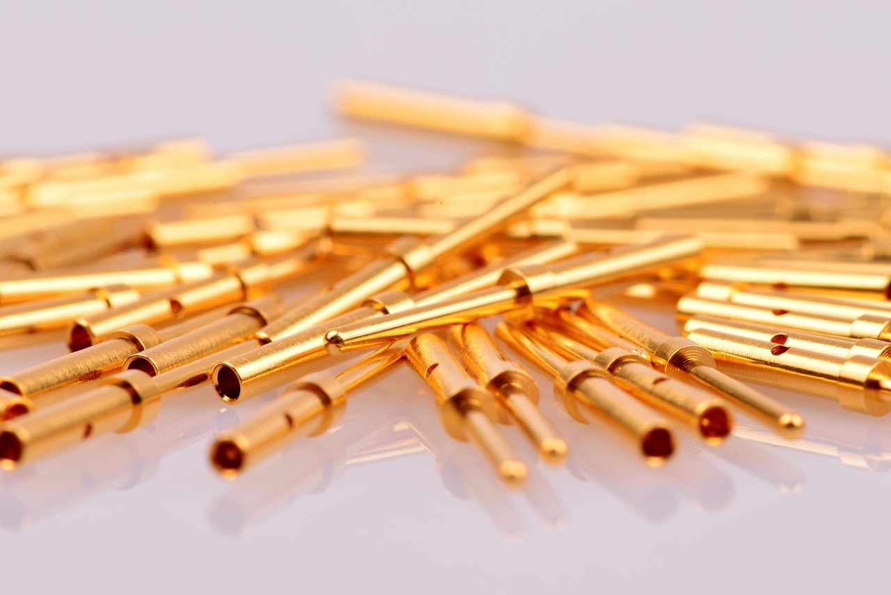
Material compatibility also matters. Tin, silver and gold plating each have use cases, cost profiles and contact-behavior implications. The mating terminal pair should be specified as a system, because mixing unapproved terminals or plating combinations can affect contact resistance and durability. For repair markets, this is one reason unidentified substitute terminals can create more risk than their low price suggests.
Common selection mistakes to avoid
- Choosing by housing appearance. Similar-looking connectors may use different terminal systems, keys, seals, materials or validation levels.
- Ignoring wire insulation diameter. A terminal may fit the conductor size while the seal or insulation crimp does not fit the actual cable.
- Using peak current as continuous current. Short-duration capability does not prove acceptable thermal behavior in continuous operation.
- Assuming sealed connectors solve every environment problem. Sealing can fail if assembly, cavity plugs, wire routing or service handling are poor.
- Mixing terminals from different systems. Unapproved substitutions can change contact force, plating compatibility and terminal retention.
- Forgetting service access. A connector that is difficult to unlatch or inspect can increase repair time and damage risk.
- Treating standards as universal approval. A standard can define test methods, but the exact vehicle program still needs application-specific validation.
A disciplined selection process should document circuit requirements, environmental exposure, mechanical constraints, applicable standards, supplier part numbers, tooling, inspection method and service instructions. That documentation helps engineering, purchasing, manufacturing and maintenance teams reduce ambiguity across the life of the vehicle platform.
Frequently asked questions
What is the difference between an electrical terminal and a connector?
The terminal is the conductive contact attached to the wire. The connector is the assembly that houses, aligns, protects and locks the terminals. In automotive wiring, the two should be selected together because terminal performance depends heavily on the housing, seals, retention features and crimp process.
Are sealed automotive connectors always better than unsealed connectors?
No. Sealed connectors are valuable in wet, dusty or exposed areas, but they can add size, cost and mating force. In a protected cabin or enclosed module, an unsealed connector may be the more suitable option if it meets the electrical and mechanical requirements.
Can the same connector be used for 12 V, 48 V and high-voltage EV circuits?
Not automatically. Voltage, current, spacing, touch protection, shielding, interlock needs and safety validation can differ significantly. A low-voltage connector family should not be moved into a higher-voltage application unless the supplier and vehicle program validation clearly support that use.
Why do connector problems sometimes appear as intermittent electrical faults?
Vibration, fretting, partial mating, terminal back-out, poor crimping or moisture ingress can create resistance changes that appear only under certain temperature, movement or load conditions. That is why mechanical retention, sealing and crimp quality are as important as the nominal electrical rating.
What information is needed before selecting automotive electrical terminals and connectors?
At minimum, define circuit voltage and current, wire size, insulation diameter, pin count, vehicle location, temperature range, sealing need, vibration exposure, mating-cycle requirement, applicable standards, tooling requirements and service access. A complete connection system should be chosen only after these factors are known.