Electrical wiring components in vehicles and how to choose them for reliable circuits
What electrical wiring components do in a vehicle
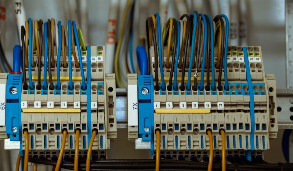
Electrical wiring components carry, connect, protect and organize power and signals inside a vehicle. They include wires, cables, terminals, connectors, fuse holders, relays, junction boxes, seals, sleeves, clips and complete harness assemblies. In older vehicles, many circuits were simple low-voltage power paths. In modern vehicles, the same wiring network may support sensors, lighting, infotainment, body control, battery systems, safety functions and high-speed data communication.
That makes component selection more than a price or package-size decision. A reliable choice must account for current load, voltage class, heat, vibration, moisture, chemicals, electromagnetic compatibility and service access. The right electrical wiring components reduce voltage drop, resist corrosion and abrasion, maintain stable contact force and help technicians trace faults without damaging the harness.
For more articles in this topic area, see the Electrical Components section.
The main component groups in an automotive wiring system
A vehicle wiring system is not a single part. It is a layered network of conductors, connection points, protective devices and mechanical supports. Each group has a specific role, and a weak choice in one area can affect the performance of the whole circuit.
| Component group | Main function | Key selection factors |
|---|---|---|
| Wires and cables | Carry electrical current or signals between devices | Voltage rating, conductor size, insulation material, temperature class, flexibility and routing length |
| Terminals and contacts | Create the conductive interface inside a connector or device | Contact resistance, plating, crimp quality, mating cycle requirement and vibration resistance |
| Connectors and housings | Provide detachable electrical and mechanical interfaces | Pin count, locking design, sealing level, polarization, temperature and serviceability |
| Seals and grommets | Block water, dust, oil mist and road contamination | Material compatibility, compression, cavity design and installation method |
| Protection devices | Limit damage from overloads, shorts and transient faults | Fuse rating, relay load, circuit location, replacement access and coordination with wire size |
| Harness coverings and supports | Protect and route wiring through the vehicle body | Abrasion resistance, heat shielding, bend radius, noise control, clips and strain relief |
These parts need to be selected as a system. A wire may have the correct ampacity, but the circuit can still fail if the terminal is poorly matched, the connector seal is undersized or the harness is routed against a sharp metal edge. Likewise, a sealed connector will not solve a problem caused by excessive voltage drop or by a fuse selected without enough margin for inrush current.
Why wiring choices are becoming more demanding
Automotive electrical architecture has become denser and more varied. Traditional 12 V systems remain common, but many vehicles also include 48 V subsystems, high-voltage traction circuits, advanced driver assistance sensors, electronic control units and multiple communication networks. These changes do not make older wiring principles obsolete, but they make assumptions more risky.
The first pressure is current density. More electrical loads in a limited package can increase heat around cables and connectors. A conductor sized only for a nominal current may run too hot if it is bundled tightly, placed near an engine, routed through a hot body cavity or exposed to long duty cycles. Temperature class and derating become practical design issues, not just catalog details.
The second pressure is signal quality. Camera, radar, infotainment and control circuits may be more sensitive to electromagnetic noise than simple lighting circuits. Shielding, twisted pairs, grounding strategy and connector continuity can determine whether a circuit remains stable in real driving conditions. Public references such as UN Regulation No. 10 address electromagnetic compatibility at the vehicle and component level, which shows why wiring layout is part of system performance.
The third pressure is environmental exposure. Water splash, road salt, oil vapor, cleaning chemicals and vibration all attack wiring components. Sealed connectors, corrosion-resistant contact finishes, abrasion sleeves and stable clip locations reduce those risks. However, sealing must be designed, not assumed. A connector that is sealed at the interface can still admit moisture through the cable side if wire seals, cavity plugs or strain relief are missing or incorrectly installed.
Standards and references that shape selection
Automotive wiring decisions are often guided by standards, customer specifications and internal validation plans. These documents are not interchangeable, and they do not remove the need for engineering judgment. They do, however, help define test methods, acceptance criteria and terminology.
Cable and wire references
ISO 19642 is a major reference family for road-vehicle automotive cables. ISO 19642-1:2023 defines vocabulary and design guidance for automotive cables and is identified by ISO as a successor to earlier ISO 6722 and ISO 14572 cable standards. In many supply chains, older drawings may still mention ISO 6722 for 60 V and 600 V single-core cables, especially where legacy platforms remain in production. SAE J1128 is also commonly referenced for low-voltage primary cable in surface vehicle electrical systems at 60 V DC or less.
For practical sourcing, this means a buyer or engineer should not simply ask for automotive wire. The drawing or specification should define conductor material, cross-section or gauge, insulation type, voltage class, temperature class, wall thickness and required test basis. If the circuit is safety-related or exposed to unusual heat or fluids, the specification should be more detailed.
Connector and terminal references
Connector systems are usually validated through performance specifications, not appearance alone. SAE/USCAR-2 covers performance testing for automotive electrical connector systems in low-voltage road-vehicle applications. It is especially relevant because many wiring problems start at the interface: loose terminals, poor crimp geometry, fretting corrosion, insufficient retention force or damaged seals.
Connector selection should therefore include both electrical and mechanical questions. Is the current rating suitable for the duty cycle? Is the housing keyed to prevent wrong mating? Does the terminal maintain contact force after vibration and thermal cycling? Are unused cavities plugged? Can the connector be serviced without breaking the lock or pulling on the wires?
Harness workmanship and safety references
IPC/WHMA-A-620 is widely used for cable and wire harness assembly acceptance. It addresses areas such as crimped, soldered and mechanically secured interconnections, as well as related harness assembly practices. For vehicle electrification, safety references such as ISO 6469 and U.S. FMVSS No. 305 become relevant to electric shock protection and electric-powered vehicle safety. These documents operate at different levels: some guide component construction, some guide assembly quality, and some guide vehicle-level safety compliance.
How to choose components for a reliable circuit
Start with voltage, current and duty cycle
The first filter is electrical load. A wire or terminal must carry the expected current without unacceptable heating or voltage drop. The answer depends on conductor size, material, insulation, ambient temperature, bundle size and circuit length. A short intermittent load, such as a washer pump, is not the same as a long-duration load, such as a cooling fan or heater element. Inrush current also matters because motors and lamps can draw more current at startup than during steady operation.
Voltage class should be treated separately from current. A component that works in a 12 V body circuit may be unsuitable for 48 V or high-voltage applications. Higher voltage can require different insulation, spacing, connector design, color coding, interlock strategy and service procedures. Do not assume that a similar-looking connector is acceptable across voltage classes.
Match insulation and sealing to the environment
Insulation protects the conductor from short circuits and environmental attack. In an engine bay, heat and oil resistance may be critical. Under the body, abrasion, water and salt exposure may dominate. In doors and tailgates, repeated flexing is a major concern. For interior electronics, flame behavior, packaging space and noise control may matter more. See also: Buying Guides.
Sealing choices should follow the actual exposure. A connector inside a dry dashboard does not need the same sealing strategy as a connector near a wheel arch. In wet zones, the design should include compatible wire seals, cavity plugs, backshells or boots where needed. Over-sealing can also create issues if trapped moisture cannot escape, so drainage and orientation should be considered.
Pay attention to terminals and crimp quality
Terminals are small, but they are often among the most critical parts of a wiring system. A good crimp creates a controlled mechanical and electrical bond between the conductor and the terminal barrel. A poor crimp may look acceptable from the outside while creating high resistance, heat or intermittent faults. Key control points include strip length, wire size range, crimp height, insulation support, pull force and strand damage.
Contact plating is another selection factor. Tin, silver and gold finishes are used for different performance and cost requirements. Mixed plating, high vibration or low-current signal circuits can increase the risk of fretting or unstable resistance if not validated. For safety or sensor circuits, the lowest-cost terminal may not be the lowest-risk choice.
Design routing before finalizing the harness
Routing is where electrical design meets the physical vehicle. A harness should avoid sharp edges, moving linkages, exhaust heat, pinch points and water traps. Clips should hold the harness without crushing it. Bend radius should protect conductors and shields. Service loops should be long enough for repair access but not so long that the harness rubs or rattles.
Protective sleeves, tapes, conduits and heat shields should be selected for the local risk. A woven sleeve may help abrasion and noise control, while a corrugated conduit may help impact protection. Heat-reflective materials may be needed near exhaust or power electronics. The goal is not to add covering everywhere; it is to place the right protection at the actual failure points.
Common failure modes and what they usually indicate
Many wiring failures appear as intermittent electrical symptoms before a visible defect is found. A structured fault map helps separate component selection issues from installation or maintenance issues.
| Observed issue | Possible wiring component cause | Typical prevention method |
|---|---|---|
| Intermittent sensor signal | Loose terminal, fretting corrosion, poor shielding or damaged ground path | Validate connector retention, contact finish, shielding continuity and grounding layout |
| Repeated fuse opening | Short to ground, undersized wire, overload or incorrect fuse coordination | Confirm load current, routing protection, fuse rating and harness branch design |
| Connector discoloration or melting | High contact resistance, overload, poor crimp or insufficient current rating | Check terminal size, crimp parameters, current derating and mating condition |
| Corrosion in connector cavities | Seal damage, missing cavity plug, wrong connector orientation or water pooling | Improve sealing, add cavity plugs, review drainage and control assembly handling |
| Broken wire near a hinge or moving part | Insufficient flex life, tight bend radius or lack of strain relief | Use flexible cable, adjust bend radius and add strain relief or routing guides |
| Noise in communication lines | Poor shielding, untwisted routing, ground loop or proximity to high-current cables | Separate noisy circuits, maintain twist, control shield termination and improve grounding |
This table is not a substitute for diagnostic testing. It does show why wiring reliability has to be considered before production. Many defects are not caused by a single bad component. They come from a mismatch between component capability, circuit demand and vehicle environment.
A practical checklist for buyers and engineers
When reviewing electrical wiring components for a vehicle project, a short checklist can prevent costly ambiguity. The most useful questions are specific and verifiable:
- What nominal voltage, maximum voltage and transient conditions will the circuit see?
- What continuous, peak and inrush current must the wire, terminal and connector carry?
- What temperature range applies at the actual installation location, not just the vehicle average?
- Will the harness face oil, fuel vapor, road salt, moisture, cleaning agents or UV exposure?
- Is the circuit a power circuit, low-current signal circuit, data line or safety-related function?
- Which standard, drawing revision or customer specification defines acceptance?
- Are connector seals, cavity plugs, locks and strain relief parts included in the bill of materials?
- Can technicians identify, disconnect and reconnect the component without damaging it?
- Has routing been checked for abrasion, heat, moving parts, water traps and service access?
- Are inspection criteria defined for crimp height, pull force, terminal seating and harness covering?
The checklist also improves communication between design, purchasing, quality and maintenance teams. A clear drawing and specification reduce the risk of substitutions that look equivalent but fail under vibration, heat or moisture. For industry content sites and parts catalogs, the same structure helps readers understand why a product category exists and what technical questions should be answered before selection.
Frequently asked questions
What are the most important electrical wiring components in a car?
The most important components are wires or cables, terminals, connectors, protection devices such as fuses and relays, seals, clips, sleeves and complete harness assemblies. Their importance depends on the circuit. A high-current load depends heavily on conductor size and terminal resistance, while a sensor circuit may depend more on stable contact, shielding and grounding.
How are automotive wires different from ordinary wires?
Automotive wires are selected for vehicle conditions such as vibration, temperature variation, fluids, abrasion and tight routing. They may use specific conductor sizes, insulation materials, wall thicknesses and temperature classes defined by road-vehicle cable standards or customer specifications. Ordinary general-purpose wire may not have the same validation for vehicle environments.
Why do connectors fail even when the wire size is correct?
A correct wire size does not guarantee a reliable connection. Connectors can fail because of poor crimping, low terminal retention, insufficient current rating, damaged seals, corrosion, vibration or mismatched plating. The connector system must be evaluated together with the wire, terminal, seal and operating environment.
Do electric vehicles need different wiring components?
Electric vehicles use many familiar low-voltage wiring parts, but high-voltage traction circuits require different insulation, spacing, connectors, safety labeling, service precautions and validation. EVs also create packaging and thermal challenges because battery systems, power electronics and charging hardware add new electrical and environmental requirements.
Is a sealed connector always better?
No. A sealed connector is better only when the environment requires it and the sealing system is correctly assembled. In dry interior locations, an unsealed connector may be easier to service and more cost-effective. In wet or dirty zones, sealing is usually important, but the design must also consider wire seals, cavity plugs, drainage, orientation and strain relief.