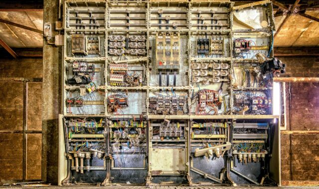
Switchgear components and their role in safer power distribution
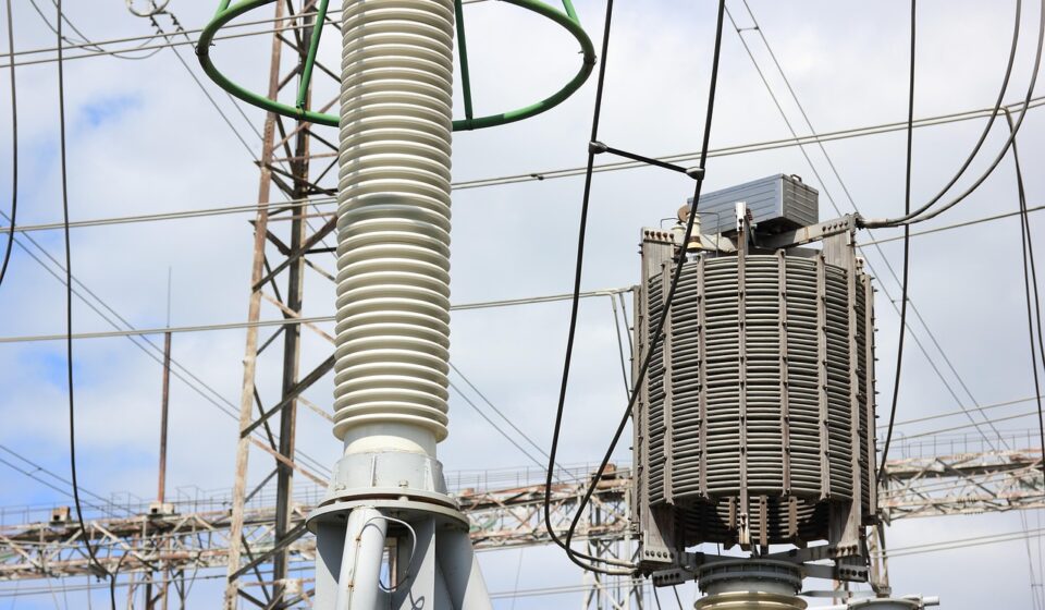
Switchgear components are the devices, conductors, controls and protective structures inside a switchgear assembly that allow electrical power to be distributed safely. Core component groups include circuit breakers or switches, busbars, fuses, relays, instrument transformers, control wiring, meters, insulation, earthing parts, interlocks and the enclosure. For factories, EV charging sites, substations and industrial power rooms, these parts affect more than the purchase price. They influence fault interruption, worker safety, uptime, inspection planning and long-term replacement decisions. Standards such as IEC 61439 for low-voltage assemblies, IEC 62271 for high-voltage switchgear and controlgear, IEEE C37 switchgear standards, UL 1558 and NFPA 70E provide useful context for how these assemblies are specified, tested and maintained.
What switchgear components do in a power system
Switchgear is used to control, protect and isolate electrical equipment. In practice, it sits between the power source and the loads that depend on reliable electricity. In an automotive plant, those loads may include production lines, compressors, robots, paint systems, battery formation equipment or EV charging infrastructure. In commercial and utility settings, the basic requirement is the same: power must be distributed, monitored and disconnected safely when operating conditions become abnormal.
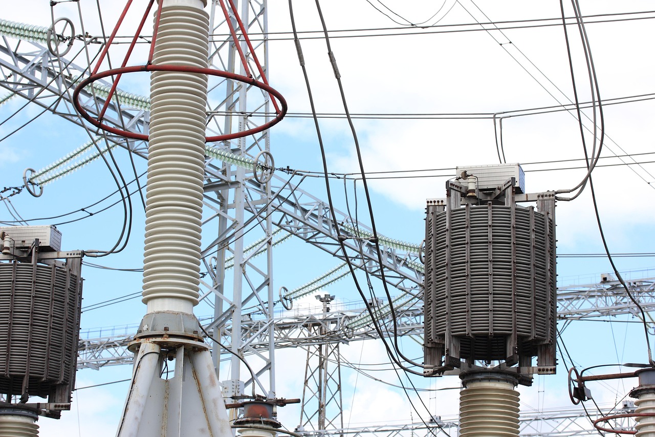
The components inside switchgear usually perform four connected tasks. First, they carry current under normal operating conditions. Busbars, cable terminations and conductors must handle rated current without excessive temperature rise. Second, they interrupt or isolate current when required. Circuit breakers, load-break switches, disconnectors and fuses are selected according to voltage, current, fault level and operating duty. Third, they measure and control the system. Relays, meters, current transformers, voltage transformers and auxiliary devices provide the information needed for protection and automation. Fourth, they contain, separate or direct energy. Enclosures, compartments, insulation, shutters, interlocks and earthing systems help reduce the chance that a fault or maintenance error will affect personnel or adjacent equipment.
For more articles on related devices, controls and power distribution hardware, visit the Electrical Components category.
The main component groups inside switchgear
Switchgear is not a single device. It is an assembly of coordinated parts. The exact layout depends on voltage class, installation environment, regional standards and application, but most systems include the following groups.
| Component group | Typical examples | Main role | Key selection point |
|---|---|---|---|
| Switching and interrupting devices | Circuit breakers, load-break switches, disconnectors, contactors, fuses | Open, close, interrupt or isolate circuits | Voltage rating, current rating, short-circuit rating and duty cycle |
| Current-carrying conductors | Main busbars, branch busbars, cable lugs, terminals | Carry load current through the assembly | Temperature rise, mechanical strength and fault withstand capacity |
| Protection and control | Protective relays, trip units, auxiliary relays, PLC interfaces | Detect abnormal conditions and command switching devices | Coordination, settings, communication protocol and testability |
| Measurement devices | Current transformers, voltage transformers, meters, sensors | Provide data for protection, metering and monitoring | Accuracy class, burden, insulation level and installation position |
| Insulation and separation | Insulators, barriers, bushings, shutters, compartments | Maintain safe electrical clearances and separation | Dielectric strength, creepage distance and contamination resistance |
| Enclosure and safety hardware | Metal enclosure, doors, locks, interlocks, grounding bar, arc ducts | Provide mechanical protection and reduce access risks | Ingress protection, accessibility, arc-resistance requirements and maintenance access |
| Auxiliary systems | Control power transformers, DC supplies, heaters, lamps, terminal blocks, wiring | Support operation, indication and environmental control | Reliability, labeling, serviceability and compatibility with control voltage |
The circuit breaker is often the most visible device, but it is only one part of the protection chain. A breaker without correct sensing, relay logic, mechanical alignment and rated conductors cannot provide reliable protection. In the same way, high-quality relays cannot compensate for undersized busbars, poor terminations or deteriorated insulation.
How standards shape component choice
Standards do not replace engineering judgment, but they help define language, ratings, tests and minimum expectations. IEC 61439-1:2020 covers general rules for low-voltage switchgear and controlgear assemblies, including service conditions, construction requirements, technical characteristics and verification requirements. In IEC-based projects, this standard is important because the assembly is evaluated as a coordinated system rather than as a loose collection of parts.
For high-voltage switchgear and controlgear, the IEC 62271 series is a major reference. It covers many categories of high-voltage equipment and helps define requirements for assemblies, switching devices and related parts. For North American medium-voltage metal-clad switchgear, IEEE C37.20.2-2025 is an active standard for metal-clad switchgear using drawout electrically operated circuit breakers. Its published scope describes equipment with rated maximum voltage levels from 4.76 kV to 48.3 kV and main bus continuous current ratings of 1200 A, 2000 A, 3000 A and 4000 A.
Low-voltage power circuit breaker switchgear in North America is often associated with UL 1558 and IEEE C37.20.1. UL 1558 covers metal-enclosed low-voltage power circuit breaker switchgear assemblies that may include low-voltage power circuit breakers, interrupting devices, switches, control equipment, instrumentation, metering and protective or regulating equipment. Its scope covers equipment rated 1000 V ac or less nominal, with 1058 V ac maximum. The standard was published in April 2025 and revised in June 2026, so buyers comparing documents should verify the exact edition referenced in a project specification.
Safety practices are separate from component ratings, but closely related. NFPA 70E addresses electrical safety-related work practices and risk reduction for hazards such as electric shock, arc flash and arc blast. It does not make a poorly selected component suitable for service, but it does influence how equipment is assessed, labeled, maintained and approached by qualified workers.
Selection criteria that matter beyond the part number
When replacing or specifying switchgear components, the part number is only the starting point. A component must match the electrical, mechanical and environmental conditions of the assembly.
- Voltage and insulation level: Devices, barriers and wiring must be suitable for the system voltage and expected overvoltage conditions. Clearance, creepage and dielectric withstand requirements become more critical as voltage rises.
- Continuous current and temperature rise: Busbars, breakers, switches and terminals must carry expected load current without overheating. Ambient temperature, enclosure ventilation and harmonic content can affect real operating temperature.
- Short-circuit withstand and interrupting rating: Components must withstand or interrupt available fault current. This requires attention to interrupting rating, momentary withstand, short-time withstand and protective coordination.
- Mechanical compatibility: Drawout breakers, shutters, racking mechanisms, door interlocks and mounting hardware must align correctly. A device that appears electrically similar may still be mechanically unsuitable.
- Protection coordination: Trip units, relays, fuses and downstream devices should operate in a coordinated sequence. Poor coordination can cause unnecessary outages or leave equipment exposed to excessive fault energy.
- Environment: Dust, moisture, salt, vibration, temperature swings and chemical exposure can degrade insulation, contacts and auxiliary wiring. Industrial and automotive manufacturing environments often require more attention to contamination and thermal cycling than clean indoor electrical rooms.
- Maintainability: Components should be accessible for inspection, testing and replacement without unnecessary disturbance to adjacent energized or safety-critical parts.
Current market conditions also make documentation more important. The International Energy Agency’s 2026 grid analysis states that electricity demand has been growing faster than overall energy demand and that grid investment must rise significantly by 2030 to keep pace with electrification, data centers, industrial growth and system expansion. That does not mean every switchgear component is unavailable, but it does make accurate specifications, approved equivalents and spare-parts planning more valuable.
Low-voltage and medium-voltage component differences
Low-voltage and medium-voltage switchgear serve the same broad purpose, but their component design priorities are different. Low-voltage assemblies often emphasize high current, selective coordination, compact layout and integration with building or plant distribution. Medium-voltage assemblies place heavier emphasis on insulation coordination, compartmentalization, drawout mechanisms, earthing, shutters and controlled access to energized sections.
| Area | Low-voltage switchgear | Medium-voltage switchgear |
|---|---|---|
| Typical standards context | IEC 61439, UL 1558, IEEE C37.20.1 | IEC 62271 series, IEEE C37.20.2 and related C37 standards |
| Common interrupting device | Low-voltage power circuit breaker, molded-case breaker or fuse, depending on assembly type | Vacuum circuit breaker, load interrupter switch or fused switch, depending on design |
| Key design concern | Current carrying capacity, heat, coordination and service access | Insulation level, compartmentalization, switching duty and safe isolation |
| Measurement and protection | Trip units, metering, current sensors, relays in larger systems | Protective relays, current transformers, voltage transformers and control power systems |
| Maintenance focus | Connections, contacts, trip testing, ventilation, thermal scanning and labeling | Breaker mechanism, racking system, insulation condition, shutters, interlocks and relay testing |
This difference matters because component substitution across voltage classes is not acceptable. Even within the same voltage class, a component approved for one assembly may be unsuitable for another if it changes heat performance, short-circuit withstand, internal clearances or certification status. See also: Buying Guides.
Common failure modes and inspection priorities
Many switchgear problems develop gradually. Loose or corroded joints can increase resistance and create localized heating. Contact wear can reduce interrupting performance or cause nuisance operation. Dust and moisture can reduce insulation performance. Aging control wiring, weak auxiliary relays or failing control power supplies can prevent breakers from closing or tripping when needed. Mechanical wear in shutters, handles, springs and racking systems can turn routine operation into a safety concern.
Inspection priorities should follow site procedures and applicable safety standards, but several checks are widely relevant. Visual inspection can identify discoloration, cracked insulation, missing barriers, blocked ventilation, moisture marks or damaged labels. Thermographic inspection under load can help identify abnormal heating at joints and conductors. Electrical tests can verify insulation resistance, relay operation, breaker timing, trip functions and contact resistance where appropriate. Mechanical checks can confirm that interlocks, shutters, hinges and racking systems move correctly.
Maintenance should be performed only by qualified personnel using approved procedures. An enclosure does not eliminate arc flash or shock risk. Before opening compartments, replacing parts or changing settings, workers should follow the facility’s electrical safety program, lockout and tagout procedures, equipment labels and risk assessment requirements.
A practical checklist for procurement and replacement
For purchasing teams, maintenance planners and engineers, the safest approach is to treat switchgear components as part of a verified assembly. The following checklist can reduce errors before an order is placed.
- Record the assembly nameplate data, including manufacturer, model, voltage, current, short-circuit rating and applicable standard.
- Identify the exact component function, not only its visible shape or catalog number.
- Confirm whether the replacement affects listing, certification, type testing or assembly verification.
- Check electrical ratings, mechanical dimensions, mounting method, terminal arrangement and control voltage.
- Review protection settings, relay curves and coordination requirements before changing protective devices.
- Confirm environmental requirements such as ingress protection, corrosion resistance, heater needs or ventilation limits.
- Keep records of test reports, manuals, drawings, wiring diagrams and maintenance history.
- Use approved equivalents only after engineering review, especially for breakers, busbar parts, CTs, VTs, relays and insulation components.
This disciplined approach is especially important in facilities where production downtime is expensive. In automotive-related operations, a single distribution failure can stop multiple processes at once. Reliable switchgear component management supports both electrical safety and operational continuity.
Frequently asked questions
What are the most important switchgear components?
The most important switchgear components are the interrupting device, busbars, protection and control devices, instrument transformers, insulation system, earthing parts, enclosure and interlocks. Their importance depends on the application, but they must work together as a coordinated assembly.
Are switchgear and controlgear the same thing?
The terms overlap but are not identical. Switchgear generally refers to equipment used to switch, protect and isolate power circuits. Controlgear is often associated with controlling equipment such as motors and process loads. Many standards and assemblies use the combined term switchgear and controlgear because switching, protection and control functions are frequently integrated.
Can a switchgear component be replaced with a similar-looking part?
Not safely without verification. A similar-looking part may have a different interrupting rating, heat performance, insulation properties, mounting dimensions, control voltage or certification status. Replacement should be checked against the original assembly documentation and applicable engineering requirements.
Why are switchgear components relevant to automotive electrical systems?
Automotive manufacturing, EV charging, battery production and test facilities require reliable power distribution. Switchgear components help control high electrical loads, isolate faults and protect equipment. As electrification increases power demand in and around automotive facilities, component selection and maintenance become more important.
How often should switchgear components be inspected?
Inspection intervals depend on the equipment type, environment, loading, age, manufacturer guidance and facility safety program. Harsh environments, high load cycles, visible deterioration or past faults usually justify more frequent inspection. The interval should be set by qualified personnel using applicable standards and site risk assessment.