How to choose an electrical push button switch for automotive control panels
What an electrical push button switch does in a vehicle circuit
An electrical push button switch gives a driver, technician, or operator a direct way to open or close a low-voltage circuit. In automotive control panels, selection depends less on the outside shape of the button and more on the job it must perform: momentary command, maintained on/off control, warning acknowledgement, auxiliary lighting, start input, or equipment interlock.
A suitable switch must match the circuit current, voltage, contact logic, mounting space, user interface, and operating environment. For automotive electrical components, that means looking beyond appearance and checking sealing, vibration tolerance, terminal style, illumination, and how the control will be identified on the panel.
The selection process should start with the circuit function, then move to the operating environment and panel design. A push button that performs well inside a dry dashboard may not be suitable for an exterior work-truck panel, a trailer control box, or an off-road auxiliary system. Likewise, a signal-level button should not be used to switch a motor, lamp bank, compressor, or solenoid directly unless its contact rating and duty are clearly suitable.
Start with the switching action
The first decision is whether the push button should be momentary or maintained. This is where many selection errors begin, because the two types can look almost identical from the outside.
Momentary action
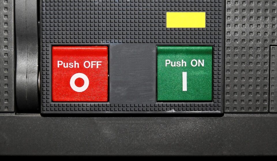
A momentary push button changes state only while it is being pressed. When the operator releases the actuator, the spring returns the switch to its normal state. This action is common for horn commands, starter inputs, reset buttons, wake-up signals, diagnostic inputs, and control signals sent to a relay, body control module, or electronic controller.
Momentary switches are useful when the circuit should not remain active without continuous human input or logic confirmation. They are also preferred when the actual load is controlled elsewhere, such as by a relay, MOSFET, control module, or timed circuit.
Maintained action
A maintained push button, often called latching, stays in its changed state after being pressed. Depending on the design, a second press, twist, or release mechanism may return it to the original position. Maintained action is better for functions that should remain on until deliberately switched off, such as auxiliary lighting, fan control, beacon lights, or non-critical accessory circuits.
The key question is whether the vehicle should remember the command mechanically at the switch or electronically in a module. Modern vehicle architectures often use momentary inputs, with software or relay logic handling the final state. Simpler aftermarket circuits and equipment panels may still use maintained switches.
Match the contacts to the circuit logic
After the action type, check the contact arrangement. Contact terms describe what happens electrically inside the switch, not the exterior style.
- Normally open means the circuit is open until the button is pressed or actuated.
- Normally closed means the circuit is closed until the button is pressed or actuated.
- SPST controls one circuit with one open-or-closed path.
- SPDT switches one common terminal between two outputs.
- DPST or DPDT can control two separate circuits at the same time.
For simple accessory control, an SPST normally open or maintained switch may be enough. Interlocks, status feedback, mode selection, or redundant circuits may require SPDT or double-pole arrangements.
If the switch is used in a safety-related function, the circuit designer should evaluate fault behavior, diagnostic coverage, and whether a normally closed or dual-channel concept is appropriate. The switch itself is only one part of that safety case.
Understand electrical ratings before choosing a style
A push button’s electrical rating should be read as a limit under stated conditions, not as a universal permission to switch any automotive load. Ratings usually specify voltage, current, load type, and sometimes electrical life. Automotive systems are commonly described as 12 V or 24 V, but real circuits can see transients, inrush current, inductive kickback, and battery charging voltage above nominal levels.
| Specification | Why it matters | Selection note |
|---|---|---|
| Voltage rating | Confirms insulation and contact suitability for the circuit | Check the DC rating, not only the AC rating |
| Current rating | Limits contact heating and wear | Account for inrush current and load type |
| Contact material | Affects performance at low signal levels and higher loads | Signal circuits and power circuits may need different contacts |
| Electrical life | Estimates switching durability under rated load | Compare it with the expected duty cycle |
| Terminal type | Influences assembly, vibration resistance, and serviceability | Use locking connectors or strain relief where needed |
If the load is a motor, solenoid, relay coil, compressor clutch, lamp group, or heater, the switch may see more stress than the steady-state current suggests. A common design approach is to use the push button as a low-current command input and let a relay or electronic power switch handle the load. This reduces contact wear and keeps high current away from the operator panel.
Design for the automotive environment
Automotive switches face conditions that consumer indoor switches rarely encounter: vibration, temperature cycling, humidity, dust, spilled liquids, cleaning chemicals, sunlight, and repeated operation with gloves. The requirements also change by location, including dashboard, engine-compartment, exterior body, trailer, marine-adjacent, agricultural, and heavy-duty truck applications.
Sealing and ingress protection
Ingress protection is often summarized with an IP code. ISO 20653:2023 addresses IP code protection for electrical equipment in road vehicles, including protection against foreign objects, water, and access to hazardous parts. IEC 60529 is the broader enclosure standard often referenced for IP ratings, while ISO 20653 includes road-vehicle-specific K designations.
For a push button, the relevant protection may apply to the front panel seal, the rear terminals, or the complete installed assembly, so the datasheet should be read carefully. A panel-mounted button advertised with a high front-face rating may still require a gasket, correct panel thickness, proper torque, and protected rear wiring. In wet or dusty areas, installation quality can matter as much as the switch body.
Temperature, vibration, and mounting location
ISO 16750-1:2023 describes environmental conditions and testing concepts for electrical and electronic vehicle equipment based on mounting location. SAE J1455, revised in 2017, is often used as a heavy-duty vehicle environmental reference for electronic equipment on trucks, buses, construction equipment, and agricultural machinery. These documents reinforce a practical point: a switch should be selected for its location, not only for the schematic.
A cab interior switch may prioritize tactile feel, illumination, and symbol clarity. A chassis-mounted or exterior control may need stronger sealing, corrosion-resistant terminals, and protection against pressure washing. A work vehicle panel may also need larger actuators for gloved operation and better resistance to impact or accidental activation.
Plan the user interface, not just the circuit
A push button is both an electrical component and a human interface. The operator must understand what it controls, whether it is active, and whether pressing it could create a safety issue.
Illuminated and non-illuminated buttons
Illuminated push buttons can show status, improve nighttime visibility, or guide the operator to a critical control. Illumination also adds design questions: LED voltage, polarity, brightness, color, dimming compatibility, current draw, and whether the lamp indicates switch position or actual load status. A light inside the button does not always prove that the controlled equipment is operating; it may only show that the switch has power. See also: Buying Guides.
For more reliable feedback, many circuits separate command indication from load confirmation. For example, a controller may light the indicator only after it detects that a relay has closed or a device is drawing current. This approach is more complex, but it reduces misleading signals.
Actuator shape and accidental operation
Flush buttons reduce snagging and accidental presses. Raised buttons are easier to find by touch. Guarded or shrouded buttons help prevent unintended operation. Mushroom-head emergency-style buttons are highly visible, but they should not be used casually for ordinary controls because operators may associate them with stop or emergency functions.
Panel cutout diameter, panel thickness, bezel shape, actuator travel, tactile feedback, and spacing all influence usability. In vehicles, these details matter because the operator may be moving, wearing gloves, working at night, or responding quickly.
Know the standards and compliance context
Several public standards and regulations are relevant when push buttons become part of a vehicle control system. In the United States, FMVSS No. 101 covers controls and displays, including requirements related to location, identification, color, and illumination for listed motor vehicle controls, telltales, and indicators. UN Regulation No. 121 addresses similar topics for identification and location of hand controls, tell-tales, and indicators in markets that apply UNECE regulations.
These rules do not turn every auxiliary button into a regulated original-equipment control, but they matter when a switch controls a listed vehicle function or is part of an OEM-level panel design. Identification should be understandable, durable, and placed on or near the control where required. For aftermarket, specialty, and work-vehicle panels, the same principles remain useful even when a specific regulation does not directly apply.
IEC 60947-5-1:2024 covers electromechanical control circuit devices and switching elements, including manual control switches such as pushbuttons. It is more closely associated with low-voltage switchgear and controlgear than with complete road vehicles, but it provides useful terminology and performance concepts for control devices. ISO 26262 may also become relevant when the switch is part of a safety-related electrical or electronic function. In that case, component selection must be integrated into a wider functional safety process rather than treated as a simple hardware choice.
A practical selection checklist
Use the following checklist before comparing part numbers or requesting samples:
- Define the function: command input, on/off control, reset, start, interlock, acknowledgement, or status control.
- Choose the action: momentary, maintained, push-pull, twist-release, or another mechanism.
- Confirm contact logic: normally open, normally closed, SPST, SPDT, DPST, or DPDT.
- Verify DC voltage and current ratings for the actual load and duty cycle.
- Decide whether the switch directly carries load current or only controls a relay or module.
- Check environmental needs: IP rating, temperature range, vibration, UV exposure, chemicals, and washdown conditions.
- Review panel requirements: cutout size, panel thickness, rear clearance, mounting hardware, and service access.
- Select terminals and wiring protection suitable for vibration and maintenance.
- Plan labeling, symbols, color, illumination, and night visibility.
- Check whether vehicle regulations or customer specifications apply to the control function.
This sequence helps avoid a common problem: choosing an attractive switch first and then trying to make the circuit and panel adapt to it. In automotive applications, the safer path is to let the function and environment narrow the choices.
Common mistakes to avoid
One mistake is assuming that a higher current number on a datasheet is always better. If that number refers to a resistive AC load, it may not describe DC automotive switching performance. Another mistake is ignoring inrush current. Lamps, motors, and capacitive loads can draw a brief surge that stresses contacts far above steady-state current.
A third mistake is treating an IP code as a complete durability guarantee. IP ratings address defined ingress tests, not every combination of vibration, heat, chemicals, sunlight, and mechanical abuse. Installation quality, gasket compression, wiring strain relief, and connector sealing can determine whether the final assembly performs as expected.
Finally, do not rely on button color alone for meaning. Color can support recognition, but clear labeling, proper placement, and consistent panel logic are more reliable. If the function affects safety, compliance, or vehicle operation, the design review should include electrical, mechanical, and human-factor considerations.
Frequently asked questions
Is a momentary or maintained electrical push button switch better for vehicles?
Neither is universally better. Momentary action is preferred for command signals, resets, horns, starts, and controller inputs. Maintained action is useful when a function should remain on without software memory, such as some auxiliary lighting or accessory circuits.
Can a push button switch control a high-current load directly?
Only if its DC rating, contact design, terminals, and duty cycle are suitable for that load. In many automotive designs, the safer and more durable approach is to let the push button control a relay, solid-state switch, or electronic module while the power device carries the high current.
Does an illuminated switch prove that the connected device is working?
Not always. Some illuminated switches only show that the switch circuit is powered or that the button is in the on position. If actual device operation must be confirmed, the circuit should use feedback from the load, relay output, sensor, or controller.
What IP rating should an automotive push button have?
The required IP rating depends on mounting location. A dry interior dashboard may need less sealing than an exterior panel, trailer box, or off-road equipment control. For road vehicles, ISO 20653 is a more specific reference for IP protection of electrical equipment than general enclosure guidance alone.
Do vehicle control identification rules apply to auxiliary switches?
They may apply if the switch controls a regulated or listed vehicle function in an OEM or regulated context. Even when an auxiliary switch is not directly covered, the principles behind FMVSS No. 101 and UN Regulation No. 121 are useful: controls should be clearly identified, visible, and understandable to the operator.