How to solder SMD components for reliable automotive electronics
What SMD soldering needs to achieve
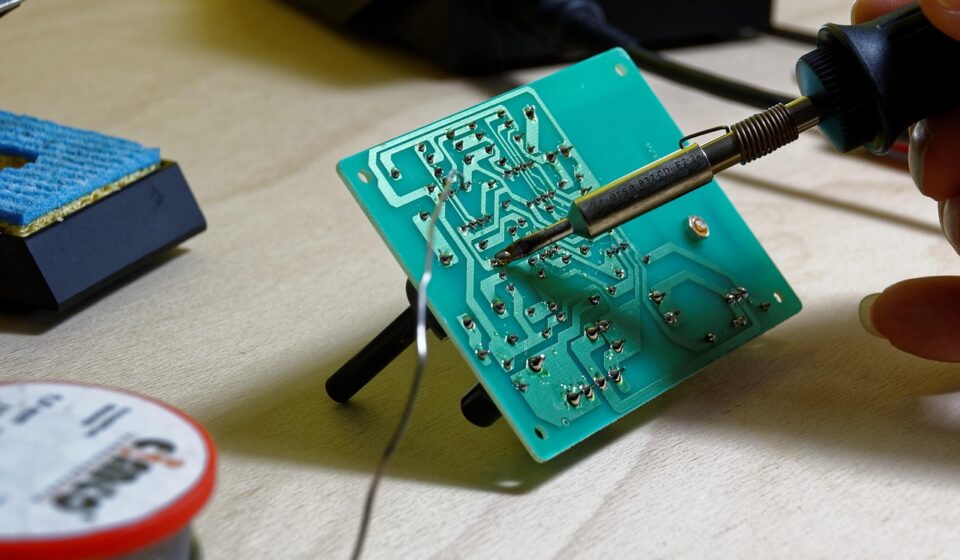
Reliable SMD soldering is not just about melting solder onto a pad. The joint must wet both the component termination and the PCB land, remain mechanically stable, avoid electrical shorts, and tolerate vibration, temperature cycling, and normal service handling. In automotive electronics, this matters because small passive parts, sensors, connectors, driver ICs, LEDs, and control modules may work close to heat, moisture, and constant movement.
A dependable SMD soldering process combines the right solder alloy, compatible flux, controlled heat, clean pads, accurate component placement, and careful inspection. This guide covers practical methods for hand work, hot-air repair, and reflow-style assembly, with a focus on solder joints used in automotive electrical components. You can also explore more in Electrical Components.
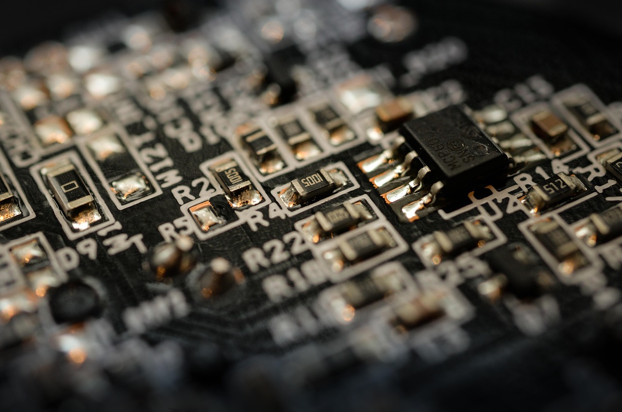
SMD soldering is common in modern vehicle electronics because surface-mount devices support compact layouts, shorter signal paths, and automated assembly. The trade-off is reduced process margin. A small bridge, overheated pad, contaminated surface, or misaligned chip resistor can create intermittent faults that are difficult to trace after the board is installed.
Why SMD soldering is different from through-hole soldering
Surface-mount devices sit on PCB pads instead of passing leads through drilled holes. This changes the thermal and mechanical behavior of the joint. In through-hole soldering, the plated barrel provides a larger solder volume and a visible fillet. With SMD parts, the solder joint is usually smaller, closer to adjacent pads, and more dependent on pad design and placement accuracy.
For automotive electrical assemblies, that difference is important. A small SMD resistor or capacitor may look firmly attached, while one end is weakly wetted or cracked. A fine-pitch IC may look acceptable from above even though solder bridges remain between pins. Hot-air repair may restore electrical continuity, but without process control it can also leave flux residue, overheated pads, or damaged nearby components.
Industry documents such as IPC J-STD-001 and IPC-A-610 are widely used as references for soldering workmanship and electronic assembly acceptability. Automotive-grade component qualification often also refers to AEC standards, such as AEC-Q100 for integrated circuits and AEC-Q200 for passive components. These standards do not replace process control, but they help define expectations for workmanship and component reliability.
For more articles on vehicle circuits, connectors, sensors, and related parts, see the electrical components section.
Tools and materials to prepare before soldering
Successful SMD soldering starts before the iron or hot-air tool touches the board. Many defects come from poor preparation, not from the final soldering step alone.
Temperature-controlled soldering iron
A fine conical, hoof, or small chisel tip can be used depending on the package size and access around the pads. The iron should be temperature controlled because uncontrolled tools can overheat pads, damage components, or produce inconsistent wetting. A very small tip is not always better. If it cannot transfer heat efficiently, the operator may keep it on the joint too long.
Hot-air rework station
Hot air is useful for removing and installing multi-pin SMD components, chip components, small ICs, LEDs, and parts with pads that are difficult to reach with an iron. Airflow should be moderate and targeted. Excessive airflow can blow away 0201, 0402, or 0603 parts and disturb nearby components.
Solder wire and solder paste
Fine solder wire is suitable for hand soldering. Solder paste is commonly used with hot plates, reflow ovens, and selected rework procedures. Lead-free solder is common in modern automotive electronics because of environmental requirements, but it generally needs higher process temperatures than traditional tin-lead solder. Mixing alloys during repair should be avoided unless the repair procedure permits it and the resulting joint can be controlled properly.
Flux
Flux removes light oxides and helps molten solder wet the pad and component termination. No-clean flux is widely used, but “no-clean” does not mean residue can be ignored in every environment. In high-impedance circuits, under components, or in harsh operating conditions, residue behavior should be considered carefully.
Magnification, tweezers, wick, and cleaning supplies
Fine tweezers, solder wick, ESD-safe brushes, lint-free swabs, and suitable cleaning solvent help prevent common defects. Magnification is especially important for fine-pitch ICs, QFN packages, small chip capacitors, and dense automotive control circuitry.
Common methods to solder SMD components
The right method depends on the component package, board density, repair objective, and production volume. The comparison below shows where each method typically fits.
| Method | Typical use | Main advantage | Main limitation |
|---|---|---|---|
| Hand soldering with iron | Chip resistors, capacitors, diodes, small IC pins, prototypes, minor repairs | Low setup cost and precise local control | Slower and harder for hidden pads or very fine pitch |
| Hot-air soldering | IC removal, small QFP/QFN work, LEDs, multi-terminal components | Heats multiple pads at once | Requires airflow and heat control to avoid disturbing parts |
| Reflow soldering | Batch assembly using solder paste and stencil | Consistent for many SMD parts when profiled correctly | Needs paste control, stencil quality, and thermal profiling |
| Hot plate or preheater support | Boards with ground planes, multilayer PCBs, repair preparation | Reduces thermal shock and improves heat balance | Still requires local soldering or reflow control |
Hand soldering small two-terminal parts
For chip resistors, capacitors, and diodes, a common method is to tin one pad lightly, position the component with tweezers, reflow the tinned pad to tack one side, and then solder the second side. After alignment is confirmed, the first side can be reheated briefly if needed. The finished joint should show smooth wetting at both ends, without excess solder balls or lifted terminations.
Drag soldering fine-pitch leads
For gull-wing IC packages, flux is essential. The operator loads a small amount of solder on the iron tip and gently drags it along the pins, allowing surface tension and flux to form separate joints. If bridges appear, solder wick and flux can remove the excess. The technique depends on steady movement, adequate flux, and avoiding pressure that bends or damages the leads.
Hot-air installation and removal
For hot-air work, the board area is usually pre-fluxed, and nearby heat-sensitive parts may need shielding. The nozzle should heat the component and surrounding pads evenly. When removing a component, it should lift only after the solder has fully reflowed; forcing it early can tear pads from the PCB. When installing a new part, alignment before full reflow is critical because small shifts can create opens or shorts.
Reflow-style assembly
In stencil-and-paste assembly, paste volume, stencil aperture design, placement accuracy, and thermal profile all interact. Too much paste can cause bridging and solder balls, while too little can create opens or weak joints. Reflow profiles are normally based on solder paste manufacturer data and component limits, with attention to preheat, soak, time above liquidus, and peak temperature.
A practical step-by-step workflow for small-batch SMD work
The following workflow is suitable for prototype assembly, board repair, and small-batch work where repeatability is more important than speed.
- Confirm the component and orientation. Check value, package size, polarity, pin 1 mark, diode direction, LED orientation, and IC marking before heating the board.
- Inspect the PCB pads. Pads should be intact, clean, flat, and free from excessive oxidation, old solder lumps, and burnt residue.
- Apply flux or solder paste appropriately. Use only enough material for the joint. Excess flux or paste can create cleaning and inspection problems.
- Stabilize the board. A board holder reduces movement and helps prevent solder paste smearing or displacement of nearby components.
- Preheat when needed. Thick copper planes, multilayer boards, and metal-core LED boards can draw heat away quickly. Gentle preheating can improve solder flow and reduce thermal stress.
- Solder with controlled dwell time. Heat the pad and termination together. Avoid pressing hard on pads or keeping heat on the joint longer than necessary.
- Inspect under magnification. Look for bridges, opens, poor wetting, skewed parts, disturbed joints, solder balls, and cracked terminations.
- Clean if the process requires it. Follow the flux manufacturer’s guidance and the reliability needs of the assembly.
- Perform electrical checks. Continuity, resistance, diode mode, insulation checks, or functional testing should match the circuit type and risk level.
This workflow does not replace a qualified production process, but it reduces common mistakes that occur when SMD repair is treated as a purely manual task. See also: Buying Guides.
Defects to watch for when soldering SMD components
Most SMD soldering problems are visible if the board is inspected carefully, but some require electrical testing or X-ray inspection. The smaller the package and the more hidden the solder joint, the more important the inspection method becomes.
Solder bridges
A solder bridge is an unintended connection between adjacent pads or pins. It is common on fine-pitch ICs when too much solder is used or flux activity is insufficient. Bridges can sometimes be removed with solder wick and flux, but repeated rework increases thermal stress.
Tombstoning
Tombstoning occurs when one end of a small chip component lifts during reflow, leaving the part standing at an angle. It is often associated with unequal wetting forces, uneven heating, uneven pad design, or paste imbalance. Very small passive components are especially sensitive.
Cold or disturbed joints
A cold joint may appear dull, grainy, or irregular, although surface appearance alone is not always conclusive with modern lead-free alloys. Disturbed joints can occur if the part moves while solder is solidifying. These defects may create intermittent resistance changes under vibration.
Insufficient wetting
Poor wetting can result from oxidation, contamination, insufficient heat, incompatible surface finish, or expired solder paste. The solder may bead up rather than spread smoothly onto the pad and termination. Adding more solder rarely fixes the root cause unless surface condition and heat transfer are corrected.
Lifted pads and delamination
Lifted pads are often caused by excessive heat, excessive mechanical force, or repeated rework. Once a pad separates from the board, repair becomes more complex and may require trace reconstruction. This is a serious concern for automotive modules where vibration can worsen a marginal repair.
Reliability considerations for automotive electronics
Automotive electronics can face temperature swings, vibration, load transients, humidity, road salt exposure, and confined mounting locations. Solder joints are only one part of the reliability picture, but they are a critical part.
Thermal cycling can expand and contract different materials at different rates. Components, solder, copper pads, and PCB laminate do not all move identically. Over time, weak joints may crack, especially on larger components or parts placed near board flex points. Vibration can also expose marginal wetting or insufficient solder volume.
Moisture sensitivity is another issue. Some plastic-encapsulated SMD packages absorb moisture before soldering. If heated too quickly or above their rated limits, internal pressure can damage the package. JEDEC moisture sensitivity and reflow classification guidance is commonly used by manufacturers to manage baking, floor life, and reflow exposure for moisture-sensitive devices.
ESD handling should not be overlooked. Many sensors, microcontrollers, communication transceivers, and driver ICs can be damaged by electrostatic discharge before they are soldered. ESD-safe work surfaces, grounded tools, packaging discipline, and operator grounding reduce the chance of latent damage that may not appear during immediate testing.
The practical point is that soldering quality cannot be judged only by whether a circuit powers on after assembly. A joint that works today may still be vulnerable if it was overheated, poorly wetted, contaminated, or mechanically strained.
Inspection checklist before the board is returned to use
- Component value, package, and polarity match the schematic or board reference.
- All visible terminations show acceptable wetting and alignment.
- No solder bridges exist between adjacent pins, pads, or exposed copper areas.
- No solder balls, clipped leads, or conductive debris remain on the board.
- Flux residue is acceptable for the application or has been cleaned properly.
- Nearby plastic connectors, labels, cables, and heat-sensitive parts show no thermal damage.
- Pads and traces remain attached and undamaged after rework.
- Electrical checks confirm no unexpected shorts, opens, or abnormal resistance paths.
- Functional testing covers the circuit behavior affected by the repaired component.
For dense or high-risk assemblies, visual inspection alone may not be enough. Hidden terminations under QFN, BGA, LGA, and some power packages may require X-ray inspection or process validation rather than simple visual review.
Frequently asked questions
Can SMD components be soldered with a normal soldering iron?
Yes. Many SMD components can be soldered with a temperature-controlled iron, especially chip resistors, capacitors, diodes, and leaded IC packages. Very small parts, hidden-pad packages, and dense boards may require hot air, preheating, magnification, or reflow equipment.
What temperature should be used to solder SMD components?
There is no single correct temperature for every SMD job. The setting depends on solder alloy, tip size, board copper mass, component limits, and flux type. Lead-free work usually needs more heat than tin-lead work, but the safest approach is to use the lowest effective temperature and shortest practical dwell time that produces proper wetting.
Is hot air better than an iron for SMD soldering?
Hot air is better for some tasks, such as removing multi-pin parts or heating several pads at once. An iron is often better for single joints, small corrections, and two-terminal parts. In practice, many technicians use both methods depending on the component and board layout.
Why do small SMD parts move during soldering?
Small components can move because of surface tension, uneven heating, excess solder, too much airflow, or unstable tweezer pressure. Reducing airflow, using proper paste volume, tacking one side first, and keeping the board stable can help.
What is the most important habit for reliable SMD soldering?
The most important habit is controlled preparation and inspection. Clean pads, correct flux, suitable heat, accurate placement, and magnified inspection together matter more than any single tool setting. Reliable soldering is a process, not just a moment of melting solder.