Electrical box components and their role in automotive circuit protection
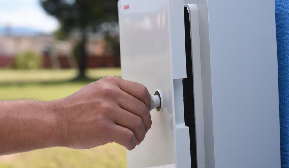
What electrical box components do in a vehicle
Electrical box components include the enclosure, cover, terminals, busbars, circuit protection devices, connectors, seals, fasteners, and identification features that keep power and signal circuits organized, protected, and serviceable. In automotive and mobile equipment, the same box may be exposed to vibration, splash water, road dust, thermal cycling, and chemical contamination. Selection is therefore more than a packaging decision. Each part inside and around the box has to support the electrical load, mounting environment, service method, and applicable standard. A sound circuit design can still become unreliable if the enclosure has weak seals, undersized terminals, poor cable control, or unclear labeling.
For buyers, engineers, and maintenance teams comparing electrical components, the most practical way to evaluate an electrical box is to separate its functions: mechanical protection, electrical distribution, circuit interruption, environmental sealing, connection management, and inspection access. This article focuses on those functions rather than treating the box as only a plastic or metal shell.
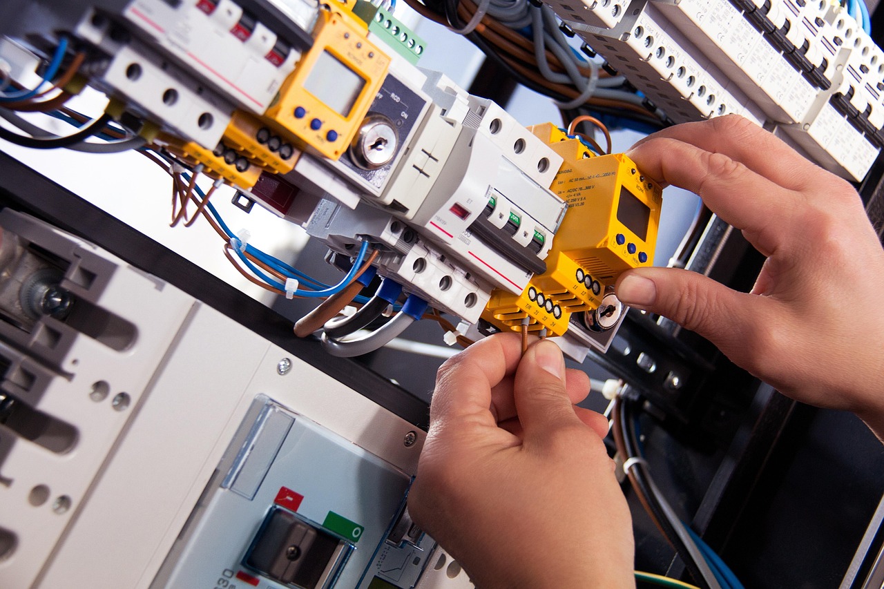
Core electrical box components and their functions
An electrical box is often specified by its enclosure rating, but reliability usually depends on smaller parts working together. The following component map applies to many automotive fuse boxes, relay boxes, junction boxes, battery distribution boxes, and compact control boxes used in vehicles and mobile equipment.
| Component | Main role | Selection risk to check |
|---|---|---|
| Enclosure body | Provides the structural shell and protects internal circuits from contact, impact, dust, and water. | Material, wall thickness, mounting method, heat exposure, and chemical resistance. |
| Cover or lid | Allows inspection and service while keeping live or sensitive parts protected during normal operation. | Latch strength, screw retention, hinge durability, and whether the cover closes evenly. |
| Gasket or seal | Compresses between housing surfaces to reduce ingress of water, dust, and contaminants. | Compression set, aging, oil exposure, ozone, temperature cycling, and incorrect groove design. |
| Terminal blocks and studs | Create fixed connection points for wires, cable lugs, sensors, or branch circuits. | Current rating, torque specification, plating, creepage distance, corrosion, and loosening under vibration. |
| Busbars | Distribute higher current more compactly than bundled wires. | Cross-section, temperature rise, insulation, short-circuit withstand, and contact surface condition. |
| Fuses and circuit breakers | Interrupt overcurrent conditions to reduce damage to wiring and connected devices. | Incorrect amp rating, poor holder contact, heat buildup, nuisance opening, or slow fault clearing. |
| Relays and contactors | Switch loads that are too high or too frequent for small control switches. | Coil voltage, contact rating, arc suppression, mounting orientation, and heat near adjacent parts. |
| Connectors | Provide detachable electrical interfaces for harnesses, sensors, modules, and accessories. | Terminal retention, seal compatibility, mating cycles, keying, plating, and strain relief. |
| Cable glands and strain relief | Control wire entry points and reduce pull force on terminals. | Incorrect cable diameter range, loose compression, sharp edges, and loss of enclosure rating at penetrations. |
| Labels and circuit markers | Support diagnosis, service, traceability, and safer replacement. | Unclear numbering, labels that peel under heat or oil, and missing fuse or relay identification. |
The table shows why a box should not be judged only by size or appearance. A compact box with a clear busbar path, secure terminals, controlled cable entry, and serviceable labeling may perform better than a larger box with poor cable management. The reverse is also true: a strong housing cannot compensate for high contact resistance or weak terminal retention.
Standards and ratings that shape component choices
Standards do not replace engineering judgment, but they help define what must be tested and how protection claims should be read. For general enclosures, IEC 60529 defines the IP Code system for degrees of protection provided by enclosures for electrical equipment, including protection against access, solid foreign objects, and water; the IEC summary states that it applies to enclosures for electrical equipment with rated voltage not exceeding 72.5 kV. (webstore.iec.ch)
Vehicle applications require additional care because a road vehicle electrical box may face pressure washing, road spray, vibration, engine-bay heat, and chemically contaminated moisture. ISO 20653:2023 is specifically titled Road vehicles — Degrees of protection (IP code) — Protection of electrical equipment against foreign objects, water and access, and its scope covers designations, requirements, and tests for vehicle electrical equipment enclosures. (iso.org)
Environmental validation is broader than water and dust protection. ISO 16750-1:2023 applies to electric and electronic vehicle systems and components, describes potential environmental stresses, and links requirements to the mounting location in or on the vehicle; the ISO summary also notes that electromagnetic compatibility is outside that part of the standard. (iso.org)
North American enclosure specifications often use NEMA enclosure Types. NEMA’s enclosure type guidance explains that Type 1 is intended for indoor protection against access to hazardous parts and falling dirt, while Type 2 adds protection against dripping and light splashing water when properly installed. (nema.org) UL 50 and UL 50E are commonly referenced for enclosures for electrical equipment, separating non-environmental and environmental considerations; UL describes UL 50E evaluation as including issues such as corrosion resistance, UV degradation, and maintaining an environmental seal on a rated enclosure. (ul.com)
Material choice can also affect compliance and validation work. UL identifies UL 94 as the standard for tests for flammability of plastic materials for parts in devices and appliances, while the UL 746 series is used for polymeric material evaluations relevant to electrical equipment. (ul.com) For connector systems, SAE/USCAR-2 covers performance testing of terminals, connectors, and components used in low-voltage road vehicle electrical connection systems, with the SAE page noting a revised December 2024 edition and a low-voltage scope of 0–20 VDC. (saemobilus.sae.org)
How automotive conditions change the selection logic
A stationary indoor junction box and a vehicle-mounted electrical box can contain similar parts, but they do not face the same risks. In a vehicle, movement and environment often matter as much as current rating. A terminal that carries the required current on a bench can still become unreliable if vibration reduces contact force or if the harness transfers load directly into the connection.
Heat and current density
Electrical boxes concentrate current paths in a limited volume. Fuses, relays, busbars, and terminal interfaces all generate heat under load. Selection should account for continuous current, peak current, ambient temperature, nearby engine or battery heat, and whether the cover restricts airflow. A practical design review should identify where heat is generated, where it can escape, and which materials or contact surfaces are likely to age fastest.
Water, dust, and chemical exposure
Sealing is more than choosing a high IP number. A box may fail at cable entries, screw bosses, latch areas, unused knockouts, or connector interfaces. In automotive environments, washdown water, dust, road salt, fuels, oils, and cleaning chemicals can all affect seals and plastics. The best rating for one mounting location may be unnecessary, or even counterproductive, in another if trapped condensation has no controlled path out.
Vibration and harness strain
Vibration can loosen screws, fret contact surfaces, fatigue soldered joints, and pull terminals out of position. Harness routing should keep cable weight away from small terminals. Strain relief should be matched to the actual cable diameter, not only the nominal wire size. Where service access is frequent, latches and connector locks should allow technicians to open the box without damaging sealing surfaces.
Serviceability and fault isolation
Automotive electrical boxes are often inspected under time pressure. A good layout allows technicians to identify circuits without guessing, replace fuses without disturbing unrelated wiring, and check torque marks or heat discoloration visually. Labels, color coding, circuit maps, and accessible test points can reduce diagnostic errors. The service view is part of design quality, not an afterthought. See also: Buying Guides.
A practical checklist for choosing electrical box components
A clear selection process reduces the risk of over-specifying one feature while missing another. The following checklist is useful before approving a box design, comparing suppliers, or replacing components in an existing assembly.
- Define the electrical load. Record continuous current, inrush current, voltage range, duty cycle, and fault protection strategy.
- Identify the mounting environment. Separate cabin, engine compartment, chassis, exterior, battery area, and washdown locations because each has different exposure.
- Choose the enclosure material. Compare metal, thermoplastic, and composite options for stiffness, corrosion, weight, insulation, flame behavior, and thermal performance.
- Verify the sealing concept. Review gasket material, compression, groove geometry, connector seals, cable glands, and unused openings.
- Check connection hardware. Confirm terminal current rating, plating, screw torque, stud size, lug compatibility, and anti-rotation features.
- Review circuit protection. Match fuses or breakers to wire gauge, load behavior, ambient temperature, and service replacement availability.
- Control harness movement. Add strain relief, clamps, grommets, bend-radius control, and routing features so vibration is not transferred to terminals.
- Plan inspection access. Make sure covers, latches, labels, and test points support maintenance without damaging the box.
- Confirm documentation. Keep drawings, material declarations, rating claims, assembly instructions, and inspection criteria together.
- Check market requirements. If the box is used in regulated equipment or exported, confirm whether RoHS, customer specifications, or vehicle-specific validation applies. EU Directive 2011/65/EU addresses restrictions on certain hazardous substances in electrical and electronic equipment. (eur-lex.europa.eu)
This checklist also helps prevent a common purchasing mistake: requesting a higher enclosure rating without checking whether the installed cable glands, connectors, drain strategy, and maintenance procedure preserve that rating in real use.
Common failure modes and inspection points
Most electrical box problems show warning signs before complete failure if maintenance teams know where to look. Heat marks around fuse clips can suggest loose contact or an overloaded circuit. Green or white residue on terminals may indicate moisture and corrosion. Flattened, cracked, or displaced gaskets can show that the cover is no longer sealing evenly. Loose cable glands may point to vibration, incorrect installation torque, or cable diameter mismatch.
Inspection should also cover the mechanical condition of the box. Mounting tabs can crack if the enclosure is used as a harness support. Covers can warp if exposed to high heat or overtightened screws. Labels can become unreadable after oil exposure or cleaning. Inside the box, uncontrolled wire bend radius can load connector backshells or terminal screws.
Replacement decisions should be based on the box’s function, not only on the part that failed. If a fuse repeatedly opens, installing a larger fuse can create a wire overheating risk. If a gasket leaks, replacing only the gasket may not solve the problem when the lid is warped or the latch no longer compresses evenly. If terminals loosen, the root cause may be torque, vibration, plating compatibility, or harness strain rather than the terminal alone.
Frequently asked questions
What are the main components inside an automotive electrical box?
The main components are the enclosure body, cover, gasket, terminals, busbars, fuses, relays, connectors, cable entry parts, strain relief, fasteners, labels, and sometimes diagnostic or monitoring features. The exact combination depends on whether the box is used for power distribution, signal junctions, relay switching, or control electronics.
Is an IP rating enough to choose an electrical box?
No. An IP rating helps describe protection against objects, dust, and water, but it does not by itself confirm thermal performance, vibration durability, connector quality, chemical compatibility, serviceability, or circuit protection. For vehicle use, the mounting location and environmental validation plan are just as important as the printed rating.
What is the difference between a junction box and a fuse box?
A junction box primarily organizes and connects circuits, while a fuse box includes overcurrent protection devices intended to open under fault or overload conditions. In practice, one automotive electrical box may combine junction, fuse, relay, and distribution functions in the same enclosure.
Why do seals fail in electrical boxes?
Seals fail because of compression set, heat aging, chemical exposure, incorrect installation, damaged sealing surfaces, poor groove design, or uneven cover pressure. Cable entries and connector interfaces can also leak even when the main cover gasket appears intact.
How often should electrical box components be inspected?
Inspection intervals should follow the vehicle or equipment maintenance plan and the severity of the environment. Boxes exposed to road spray, heat, vibration, washdown, or frequent service should be checked more often than protected cabin-mounted boxes. Useful inspection points include seals, terminals, fuse holders, cable glands, mounting tabs, labels, and signs of heat or corrosion.
Key takeaway for component selection
Electrical box components should be selected as a system. The enclosure protects the internal parts, but terminals, busbars, seals, connectors, and service features determine whether the box remains reliable after vibration, heat, moisture, and maintenance. For automotive applications, the strongest approach is to define the mounting environment first, match the electrical load and protection strategy second, and then verify that every component in the box supports the claimed rating and the real service conditions.