Circuit components in automotive electrical systems and how to select them

What circuit components do in a vehicle
Circuit components are the parts that allow a vehicle electrical system to measure, protect, switch, filter and control power. In a car, truck or electric vehicle, they include passive parts such as resistors and capacitors, semiconductor devices such as diodes and MOSFETs, integrated circuits, sensors, protection devices, connectors and the printed circuit assemblies that hold them together.
For automotive use, component selection is not based on electrical rating alone. The same part may also have to tolerate temperature swings, vibration, moisture, chemical exposure, electromagnetic interference and fault conditions over years of service. That is why component choice is closely tied to qualification standards, circuit-level validation and the actual mounting location inside the vehicle.
Main families of automotive circuit components
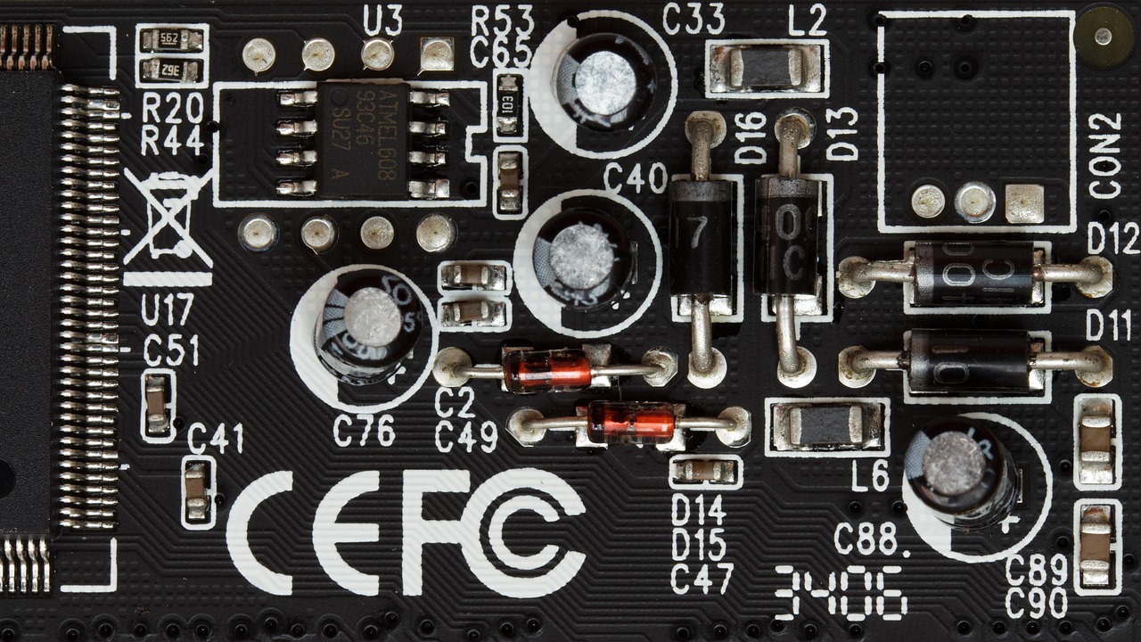
A vehicle contains thousands of individual electrical and electronic parts, but most circuit components fall into several functional families. Understanding these groups makes it easier to compare parts, read a bill of materials and judge whether a component is suitable for a demanding automotive application.
Passive components
Passive components do not create gain or perform digital logic, but they are central to stable automotive circuits. Resistors set bias points, divide voltage, sense current and dissipate controlled amounts of power. Capacitors smooth supply rails, suppress high-frequency noise and support timing or filtering networks. Inductors, chokes and ferrite parts help manage switching noise in power supplies and communication lines.
For vehicle use, passive parts are often evaluated against AEC-Q200, the Automotive Electronics Council stress test qualification document for passive components. The practical point is straightforward: a resistor or capacitor that works on a bench may not be suitable beside an engine, near a power converter or inside a door module exposed to repeated thermal and mechanical stress.
Discrete semiconductors and power devices
Discrete semiconductors include diodes, Zener diodes, transient voltage suppressors, bipolar transistors, MOSFETs, IGBTs and similar devices. They are used for rectification, reverse-polarity protection, load switching, motor control, solenoid actuation and overvoltage suppression. Because these components often carry significant current or absorb fault energy, package thermal resistance, avalanche capability, safe operating area and transient performance matter as much as headline voltage and current ratings.
AEC-Q101 is the common stress test qualification reference for discrete semiconductors in automotive applications. During selection, check the exact device revision, package, temperature grade and supplier documentation rather than assuming that every part in a product family has the same automotive status.
Integrated circuits and modules
Integrated circuits handle sensing, computation, power management and communication. Examples include microcontrollers, system basis chips, battery monitoring ICs, gate drivers, LED drivers, voltage regulators, sensor interfaces, CAN and LIN transceivers, and memory devices. As more functions move from mechanical systems to software-controlled electronics, ICs increasingly define how a vehicle monitors inputs, makes control decisions and protects itself during abnormal conditions.
AEC-Q100 is widely used for integrated circuit stress test qualification, while AEC-Q104 addresses multichip modules. These are component-level qualification frameworks. They do not prove that a complete electronic control unit will meet every system requirement, but they help reduce risk before the component enters a vehicle-level design.
Protection, sensing and interconnection parts
Protection devices include fuses, resettable protectors, TVS diodes, common-mode chokes, surge absorbers, relays and high-voltage contactors. Sensing components include temperature sensors, current sensors, position sensors, pressure sensors and optoelectronic devices. Interconnection parts include terminals, headers, sockets and board-to-board or wire-to-board connectors.
These items sit at the boundary between the circuit and the wider vehicle environment. A connector with poor terminal retention, a sensor with inadequate sealing or a fuse with the wrong time-current behavior can create failures that look like circuit design problems. For more articles in this topic area, see the Electrical Components section.
Automotive conditions that change component selection
Automotive electronics face harsher and less predictable conditions than many consumer products. ISO 16750-1:2023 describes environmental conditions and testing for electrical and electronic equipment in road vehicles and emphasizes that stresses depend on mounting location. A component inside a climate-controlled cabin does not face the same temperature, vibration, humidity or chemical exposure as a device near the engine, wheel area, battery pack or exterior lighting assembly.
| Condition | Why it matters | Selection response |
|---|---|---|
| Temperature cycling | Repeated expansion and contraction can crack solder joints, packages or ceramic bodies. | Check operating range, derating, board layout and qualification data. |
| Voltage transients | Load dump, inductive switching and reverse polarity can exceed normal supply limits. | Use protection devices, robust input stages and realistic transient testing. |
| Vibration and shock | Mechanical stress can damage leads, joints, terminals and heavier components. | Review package mass, mounting method, strain relief and PCB support. |
| Moisture and contamination | Condensation and residues can create leakage paths or corrosion. | Consider sealing, coating, creepage distance and cleaning controls. |
| Electromagnetic noise | Switching converters, motors and radios can disturb sensitive circuits. | Use filtering, shielding, grounding strategy and EMC-oriented layout. |
Electromagnetic compatibility deserves specific attention because one module can disturb another even when both appear to work correctly on their own. UNECE Regulation No. 10 addresses electromagnetic compatibility for vehicles, and SAE J1113/1 covers measurement procedures and limits for components across defined frequency ranges. For designers and buyers, this means a circuit component is not judged only by whether it turns on; it is also judged by whether it behaves predictably in the surrounding electrical ecosystem.
How standards shape circuit component choices
No single standard makes a circuit component automatically suitable for every automotive design. Standards are better understood as layers of evidence. AEC documents focus on component qualification. ISO 26262 focuses on functional safety for safety-related electrical and electronic systems in production road vehicles. ISO 16750 addresses environmental conditions and testing. IPC standards and automotive addenda support printed board fabrication, soldering and assembly acceptability. EMC references such as UNECE R10 and SAE J1113 help define emissions and immunity expectations.
| Reference | Primary role | What it does not replace |
|---|---|---|
| AEC-Q100 | Stress test qualification for integrated circuits. | System-level safety analysis or vehicle validation. |
| AEC-Q101 | Stress test qualification for discrete semiconductors. | Thermal design and fault-energy analysis in the final circuit. |
| AEC-Q200 | Stress test qualification for passive components. | Application-specific derating and board-level reliability checks. |
| ISO 26262 | Functional safety framework for safety-related E/E systems. | Component purchasing approval by itself. |
| ISO 16750 | Environmental conditions and testing guidance for vehicle electronics. | EMC testing, which is handled by other references. |
| IPC J-STD-001 and IPC-A-610 automotive addenda | Assembly and acceptability expectations for electronic assemblies. | Electrical performance validation of the finished module. |
A common mistake is treating qualification as a universal guarantee. The Automotive Electronics Council states that its documents define common qualification and requalification requirements for electrical components, but final approval for a part in a specific application remains a user and system responsibility. In other words, component qualification reduces risk; it does not remove the need for design review, testing, traceability and change control. See also: Buying Guides.
A practical selection workflow
When selecting circuit components for automotive electrical systems, the most useful workflow starts with the circuit function and ends with validation evidence. It should not start with the lowest-price part that appears to match a voltage or resistance value.
- Define the circuit role. Identify whether the part is performing power conversion, protection, sensing, communication, timing, filtering, switching or isolation.
- Map the vehicle environment. Note the mounting location, temperature range, vibration exposure, moisture risk, chemical exposure and serviceability requirements.
- Check electrical stress with margin. Compare normal operation, start-up, shutdown, fault states, surge conditions and reverse-polarity cases against the part data.
- Apply derating rules. Avoid running components continuously at their absolute maximum ratings. Heat, aging and tolerance stack-up can quickly consume margin.
- Confirm qualification status. Verify the exact AEC or other automotive qualification for the specific part number, package and revision.
- Review manufacturing compatibility. Make sure the component can survive the soldering process, cleaning process, board flex and inspection criteria used by the assembly supplier.
- Validate at circuit and module level. Test the final design under realistic supply, thermal, EMC and mechanical conditions.
- Control substitutions. Do not replace a qualified component with a similar-looking alternative unless the electrical, mechanical, material and qualification differences have been reviewed.
This workflow applies to both new design and replacement evaluation. In aftermarket or repair contexts, the safest comparison is not simply shape, color or printed marking. It is the combination of rating, package, function, qualification, tolerance, temperature grade and installation environment.
Common failure modes and what they suggest
Failure analysis often starts by asking whether the component was weak, the circuit overstressed it or the environment exceeded the design assumption. The same visible symptom can have different root causes, so conclusions should be based on evidence rather than appearance alone.
| Observed issue | Possible component-level cause | Possible system-level cause |
|---|---|---|
| Cracked ceramic capacitor | Board flex sensitivity or package stress. | Poor PCB support, connector insertion force or vibration. |
| Burned resistor | Insufficient power rating or surge rating. | Short circuit, incorrect supply voltage or thermal concentration. |
| Shorted TVS diode | Repeated surge absorption beyond capability. | Uncontrolled load dump, inductive switching or wrong placement. |
| MOSFET overheating | High on-resistance, weak package thermal path or gate stress. | Insufficient heat sinking, slow switching or overloaded actuator. |
| Connector intermittency | Terminal plating, retention or contact force issue. | Harness movement, water ingress or improper mating. |
The useful distinction is between component qualification and circuit validation. A qualified component may still fail if the application exceeds its mission profile. Conversely, a design that passes a short functional test can still be unreliable if parts are underspecified for long-term thermal cycling, surge energy or vibration. Reliable automotive electronics require both qualified parts and validated use conditions.
What buyers and engineers should check in documentation
Datasheets and certificates should be read carefully, especially when the same component family includes both commercial and automotive versions. Useful documentation may include an automotive-qualified datasheet, AEC qualification summary, material declaration, moisture sensitivity level, soldering profile, package drawing, reliability test summary, change notification policy and production part approval documentation where applicable.
For safety-related electronic systems, ISO 26262 work products may also influence component selection, but a general component listing does not automatically prove safety suitability. The design team still has to evaluate diagnostic coverage, failure modes, fault reaction time and the system safety concept. For electronic assemblies, IPC acceptability and soldering criteria help reduce assembly defects, but they do not replace electrical verification of the finished control unit.
Frequently asked questions
Are circuit components and electrical components the same thing?
They overlap, but they are not always identical. Circuit components usually refer to the parts used inside an electrical or electronic circuit, such as resistors, capacitors, semiconductors, ICs and protection devices. Electrical components can also include larger items such as harnesses, switches, motors, relays, terminals and connectors.
Does AEC qualification mean a part will work in any vehicle circuit?
No. AEC qualification is important evidence that a component has passed defined stress tests for its category, but the final application still needs electrical, thermal, mechanical and EMC validation. The same part may be suitable in one module and unsuitable in another if the load, temperature or fault conditions are different.
Why are automotive circuit components often more expensive than general components?
The price difference can come from wider temperature ratings, stricter production controls, qualification testing, traceability, longer availability expectations and documentation support. These factors add cost, but they also reduce the risk of field failures in harsh environments.
Which circuit components are most critical for reliability?
Criticality depends on the system. In power circuits, MOSFETs, capacitors, inductors, connectors and protection devices often dominate reliability risk. In sensing or control circuits, ICs, reference components, connectors and grounding elements may be more important. Safety-related circuits require a formal failure-mode review rather than a simple component ranking.
Can a non-automotive component be used in a vehicle?
It may be used in some non-critical or controlled applications, but it increases review burden. The engineer or buyer must understand the environment, expected life, failure consequences and available evidence. For production automotive electronics, qualified automotive-grade parts are generally preferred because they provide clearer reliability and traceability support.
Key takeaway
The right automotive circuit components are chosen through a combination of function, environment, qualification and validation. A part number that matches the basic electrical value is only the starting point. For reliable vehicle electronics, the better question is whether the component can perform its role under real operating stresses, within the final circuit, for the expected service life.