How to choose solder for electrical wires in automotive repairs
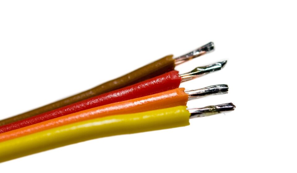
What matters when choosing solder for electrical wires
The right solder for electrical wires is usually a rosin-core electronics solder selected for the wire material, service environment and compliance requirement. For most modern electrical and automotive work, lead-free tin-based solder such as SAC or tin-copper is preferred where RoHS-style restrictions apply. Tin-lead solder may still appear in repair, hobby or exempt applications where its use is legally permitted.
The larger question is whether solder should be used at all. In vehicle harnesses, a correctly specified crimp, sealed splice or terminal is often preferred because it handles vibration better. Solder is more suitable for controlled electronics work, certain terminals, shield terminations and repairs that can be mechanically supported and sealed.
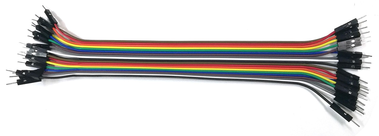
For more articles on connectors, wiring and vehicle electrical parts, visit the Electrical Components section.
Lead-free and tin-lead solder are different choices, not simple upgrades
Solder joins copper conductors by wetting the metal surface and forming a conductive metallic bond. The alloy affects melting behavior, joint appearance, working temperature and regulatory fit. Traditional 60/40 tin-lead solder and eutectic 63/37 tin-lead solder became common because they flow smoothly and melt at relatively low temperatures. The eutectic 63/37 alloy changes directly from liquid to solid at about 183 °C, reducing the pasty stage and making hand soldering easier in many cases.
Lead-free solders generally need higher tip temperatures and closer attention to heat transfer. Common electronics alloys include SAC305, a tin-silver-copper alloy, and simpler tin-copper alloys. They are widely used because restrictions on lead in electrical and electronic equipment have moved much of the industry toward lead-free assembly. The EU RoHS framework, for example, restricts lead in homogeneous materials to 0.1% by weight unless a valid exemption applies, and the European Commission describes exemptions as time-limited and subject to reassessment.
For automotive repair, the practical issue is not whether one alloy is universally better. It is whether the solder is legal for the application, compatible with the wire and component finish, and suitable for the expected heat, vibration and corrosion exposure. Tin-lead solder may be easier to work with, but it can create compliance and handling issues. Lead-free solder may satisfy a purchasing or environmental requirement, but it requires better temperature control and technique.
Use the right flux and avoid acid-core solder
Flux is as important as the alloy. Copper forms surface oxides that stop solder from wetting properly. Flux removes or disrupts those oxides during heating so solder can flow into the strands or across the terminal surface. For electrical wires, rosin or no-clean electronics flux is the normal choice. Acid-core solder is intended for plumbing or sheet metal work, not electrical wiring, because aggressive residues can continue attacking copper and terminals after the joint cools.
Rosin-core solder is convenient for small wires because the flux is inside the solder wire. However, the flux core alone may not be enough on oxidized conductors, older tinned copper, large lugs or surfaces exposed to oil and dirt. In those cases, cleaning and a compatible supplemental electronics flux may be needed. Compatibility matters: flux residue, insulation material and the sealing method all need to work together.
OSHA guidance on solder and flux fumes also highlights a practical workplace issue. Flux smoke is not just an odor; it is a process exposure that should be controlled through ventilation, suitable work practices and safety data sheet review. Lead-containing solder adds further hygiene requirements, including avoiding hand-to-mouth contact and managing waste responsibly.
Automotive wiring changes the decision because vibration matters
A solder joint can be electrically sound and still be a poor choice if the wire is expected to flex. Stranded automotive wire is used because it tolerates movement better than a solid conductor. When solder wicks into the strands beyond the joint, it can create a stiff section next to a flexible section. That transition point becomes a stress concentration under vibration, door movement, engine motion or harness bending.
This is why automotive harness standards and OEM practice often emphasize crimped terminations for cable-to-terminal connections. SAE/USCAR-21, for example, is written for validating solderless crimped connections on stranded automotive copper wire and describes test intent around mechanical strength and electrical stability over a vehicle life assumption. IPC/WHMA-A-620 also covers cable and wire harness assemblies, including crimped, mechanically secured and soldered interconnections, but it does not make every soldered splice a suitable automotive repair.
The working rule is straightforward: if a wire will move, choose a connection method that preserves flexibility, or add strain relief so the soldered area cannot flex. A soldered splice buried in a vibrating harness without support is risky. A soldered terminal on a supported electronics assembly is a different situation.
| Connection situation | Preferred approach | Why it matters |
|---|---|---|
| Automotive harness splice in a moving area | Sealed crimp splice or OEM-approved repair method | Maintains flexibility and resists vibration when made with the proper tool |
| PCB wire connection or small electronics lead | Rosin-core electronics solder | Controlled joint geometry and limited mechanical movement |
| Battery cable lug or high-current terminal | Specified crimp or approved lug process | Requires predictable resistance, pull strength and heat management |
| Shield drain or braid termination | Approved solder sleeve, crimp sleeve or harness standard method | Needs electrical continuity without damaging insulation |
| Temporary diagnostic repair | Reversible mechanical connection where safe | Avoids creating hidden permanent changes before fault confirmation |
How to match solder to wire size, insulation and temperature
Wire size changes soldering behavior. Thin signal wires heat quickly and are easy to damage. Larger conductors pull heat away from the joint and can tempt technicians to overheat the insulation. In automotive wiring, insulation families such as PVC and cross-linked polyolefin have different temperature ratings, and nearby components may include seals, connector housings or heat-shrink tubing that cannot tolerate prolonged heat.
The solder diameter should fit the work. Fine solder gives better control on small wires and terminals. Large-diameter solder can put too much alloy into the joint, encouraging wicking and bulky splices. For hand wiring, many technicians use smaller solder wire and feed it gradually after the conductor and terminal are hot enough to melt solder by contact.
Temperature control matters more than a single advertised iron wattage. A higher-wattage temperature-controlled iron may be safer than a weak iron because it can deliver heat quickly and then stop, reducing dwell time on the insulation. The goal is to heat the work, not to melt solder on the tip and smear it onto cold copper. If the solder balls up, looks grainy or does not flow into the prepared surface, the joint may be contaminated, underheated or poorly fluxed.
A reliable soldered wire joint needs mechanical support
Good soldering starts before the iron touches the wire. Strip the insulation without nicking strands. Keep the exposed length short enough to avoid unnecessary bare copper but long enough to make the required connection. Twist only as much as needed to organize the strands; over-twisting can create uneven wetting and stiffness. See also: Buying Guides.
Where a soldered splice is allowed, the conductors should have a stable mechanical relationship before solder is applied. Solder is not a clamp, a strain relief or a substitute for proper routing. NASA workmanship documents for high-reliability electrical connections emphasize controlled workmanship, insulation spacing and protection of exposed metal. Although aerospace rules are not automatically vehicle repair rules, the principle is useful: a soldered electrical connection should be clean, wetted, supported and protected.
A practical hand-soldering sequence is:
- Confirm that soldering is allowed for the component, vehicle area and compliance requirement.
- Select rosin-core or no-clean electronics solder, never acid-core solder.
- Clean the conductor and terminal so copper or plating is bright and free of oil.
- Use a temperature-controlled iron with a tip large enough to transfer heat efficiently.
- Heat the conductor and terminal together, then feed solder to the heated joint.
- Stop when solder wets the surfaces and the outlines of strands remain visible rather than buried in a blob.
- Hold the joint still until it solidifies to avoid a disturbed or cold joint.
- Inspect for smooth wetting, no sharp points, no stray strands and no overheated insulation.
- Seal and strain-relieve the repair with adhesive-lined heat shrink or the specified covering.
More solder does not mean more reliability. Excess solder can hide poor wetting, increase stiffness and form sharp points that damage insulation. A good joint normally shows complete wetting without a heavy lump.
Compliance and reliability questions buyers should ask
When purchasing solder for electrical wires, buyers should ask for more than alloy names. A useful specification includes alloy composition, flux type, flux activity level, solder diameter, cleaning requirement, shelf-life information and compliance statements. For manufacturers and repair networks, traceability can matter as much as solderability.
RoHS compliance is not the only concern. Tin-rich lead-free systems can raise reliability discussions around tin whiskers in electronics, especially where pure tin finishes are used. NIST has published work on tin whisker growth and lead-free electronics reliability, noting that tin is valued for solderability and conductivity but whiskers can be a reliability concern in certain finishes and environments. This does not mean every lead-free soldered wire joint will fail. It means alloy choice, component finish, conformal coating, spacing and environmental exposure should be considered in high-reliability designs.
For automotive electrical components, also consider service temperature, fluid exposure, harness movement, connector sealing and repair access. A solder that performs well on a bench can still be the wrong choice under the hood if the insulation softens, the joint is unsupported or moisture enters under the covering.
Common mistakes that cause soldered wire failures
- Using acid-core solder: corrosive residues can damage electrical conductors and terminals.
- Relying on solder for strength: the joint still needs support, routing and strain relief.
- Overheating insulation: heat-damaged insulation can crack, shrink back or lose sealing performance.
- Allowing solder to wick too far: long rigid sections create vibration-sensitive stress points.
- Skipping cleaning: oxidation, oil and old adhesive residue prevent proper wetting.
- Choosing solder only by melting point: compliance, flux, wire finish and environment are equally important.
- Mixing methods without approval: soldering a terminal designed for crimping can change its mechanical behavior and inspection criteria.
Frequently asked questions
What type of solder should be used for electrical wires?
Use electronics-grade rosin-core or no-clean solder. Lead-free tin-based solder is preferred where compliance requires it, while tin-lead solder should only be used where it is legally allowed and compatible with the repair specification. Do not use acid-core solder on electrical wiring.
Is lead-free solder better for automotive wiring?
Lead-free solder is often better for regulatory and environmental compliance, but it is not automatically more reliable in every wire repair. It usually needs a higher process temperature and careful technique. In many automotive harness locations, the connection method and strain relief matter more than the alloy alone.
Should automotive wires be soldered or crimped?
For most harness splices and terminals exposed to vibration, a properly made sealed crimp or OEM-approved repair method is usually preferred. Solder can be appropriate for electronics, shield terminations or supported joints, but unsupported soldered splices in moving harnesses should be avoided.
Why does solder sometimes fail on stranded wire?
Solder can wick into the strands and create a rigid section next to flexible wire. Under vibration or bending, the wire may fatigue at that transition. Poor wetting, overheating, contamination and lack of sealing can also cause failures.
How can a soldered wire joint be protected?
After inspection, cover the joint with suitable insulation such as adhesive-lined heat shrink, then secure the harness so the joint is not under tension or repeated bending. Protection should cover exposed metal and preserve the environmental sealing required for the vehicle location.
The practical takeaway
Choosing solder for electrical wires is a materials and application decision. Select an electronics-grade alloy and flux, confirm compliance requirements, match the process to the wire and insulation, and decide whether solder is suitable for the mechanical environment. In automotive electrical work, solder can make a clean conductive joint, but reliability depends on preparation, wetting, sealing and strain relief. When vibration, high current or production repeatability dominate the requirement, a specified crimp or sealed harness repair may be the stronger choice.